Flowserve Torex butterfly valves User Manual
Page 5
5
9.4
To replace PTFE seat rings.
1-4
See the corresponding items in section 9.2.
5.
Carefully clean the groove in the body into which
the seat ring is mounted.
6.
Make sure that the PTFE seat ring is mounted
with its L - shaped (or the sharp corner) side
towards the retainer ring.
7.
The disc must be turned 180˚ before the retainer
ring is placed in the valve. When the seatring is
correctly positioned into the retainer ring, place
the package in the valve.
8.
Carefully fasten the retainer ring, but do not
tighten it.
9.
Close the disc for centering the seatring,
screw down the retainer ring to keep the
seatring in place.
10.
Check that the seatring is centered. The play
shall be evenly applied between the disc and the
body.
Start to fasten the retainer ring by crosswisely
changing screws with evenly applied force.
11.
The retainer ring shall more or less flush with the
valve body. If not, gently hammer with a plastic
hammer at the same time as the screws are
tightened.
12.
Now you can mount the actuator and adjust the
end positions of the actuator until you get the
correct A-measure. This is described separately
below.
The valves seat ring should now be correctly prepared and
should not leak. Please note that PTFE can leak before it
becomes warm and adjusts to the disc. This is however a
small leakage and should not be considered. The valve
will be tight shortly.
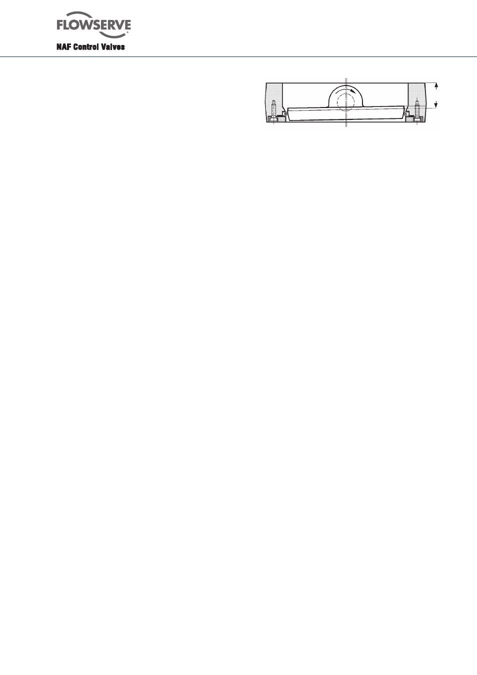
9.5
To adjust a new seat ring in a valve with
manual operating lever or worm gear unit
1.
Close the valve to the sealing position
corresponding to the value of dimension ”A”
shown in Fig. 4.
2.
Adjust the end stop of the operating lever or the
worm gear unit so that the sealing position will
not be exceeded.
3.
Tighten the retainer ring bolts in diagonally
opposite pairs.
Fig. 4. Adjusting a new seat ring.
9.6
To adjust the seat ring in a valve with
pneumatic actuator
1.
Turn the valve to closed position, although
without applying a sealing torque. The valve disc
should then only just be in contact with the seat
ring in the valve body.
2.
Adjust the end position stop to the position in
which the valve is almost closed.
3.
Connect the compressed air supply to the
actuator. If the end position stop is correctly set,
the valve disc will not move.
4.
Adjust the end position stop until the actuator
has turned the valve disc to the sealing position,
i.e. dimension ”A” shown on the valve in
accordance with section 9.4 and Fig. 4.
5.
Lock the end position stop so that the sealing
position will not be exceeded.
6.
Tighten the retainer ring bolts.
9.7
To change the upper shaft seal of O-ring type
If the shaft seal is leaking, change the upper O-ring
(16 and 18). The valve need not be removed from the
pipework for this work.
Make sure that the valve is not under pressure.
1.
If an actuator is fitted to the valve, remove it.
Begin by removing the valve positioner.
This can easily be done after the plastic cover of
the valve positioner has been removed.
Remove the four bolts securing the valve
positioner to the actuator. Then remove the nuts
securing the actuator to the valve mounting plate
and dismantle the actuator.
2.
Remove the keys.
3.
Remove the bolts securing the cover (3) and
remove the cover. Then remove the O-rings.
4.
Clean the surfaces of the shaft, cover and the
recess in the valve body.
A