9refurbishment instructions (cont.), 9refurbishment instructions, 10 valve assembly torques – Flowserve F53 Series Flanged DIN Reduced Bore Ball Valve User Manual
Page 2
8 - 11
150mm (6")
210 - 220
200mm (8")
23 - 28
300 - 310
250mm (10")
35 - 40
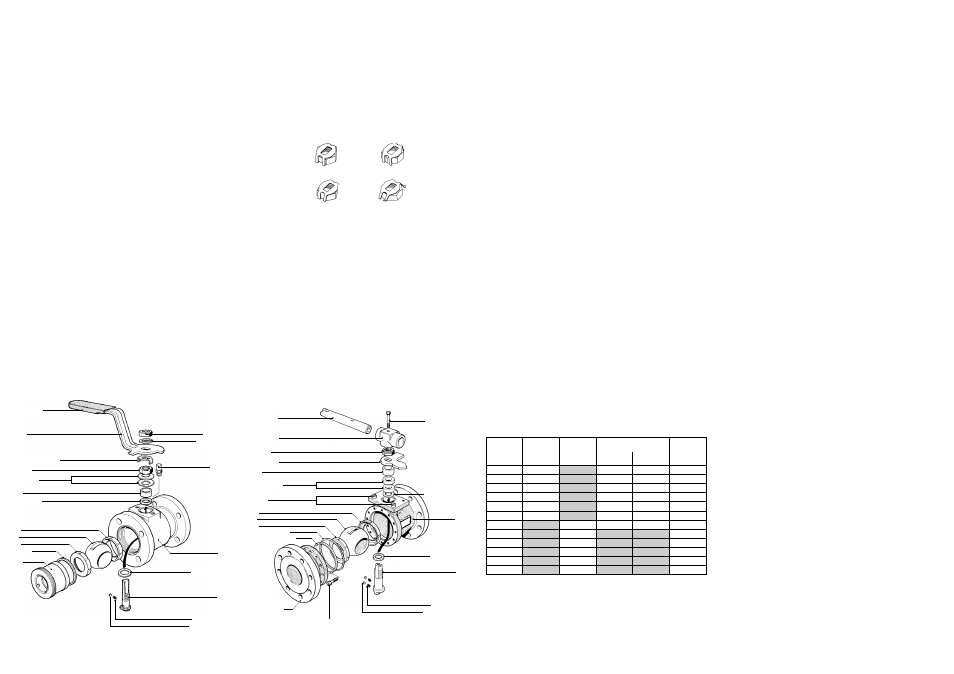
GLAND NUT TORQUES
(Nm)
GRAPHITE
BUILD
PTFE
BUILD
5 - 7
5 - 7
6 - 10
8 - 12
8 - 12
21 - 26
6 - 9
6 - 9
8 - 12
13 - 18
13 - 18
19 - 24
6 - 10
8 - 12
85 - 95
55 - 65
55 - 65
85 - 95
INTERFACE FAS-
TENING
TORQUES
(Nm)
STEM
ASSEMBLY
TORQUES
(Nm)
9
REFURBISHMENT INSTRUCTIONS (cont.)
9.2
SIZE 65mm - 250mm (2½" - 10")
9.2.1
DISMANTLING
a)
Ensuring that it is correctly supported, remove the valve from the pipeline by extracting the flange bolting from
each end. Large pipelines have a tendency to spring the flanges together making removal difficult. If necessary,
remove or loosen elbows, couplings or pipe supports to get extra
manoeuvrability.
b)
With the valve securely clamped and in the open position, undo the fastenings retaining the two body parts.
c)
Tap one of the flanges sharply with a mallet to break the joint and separate.
d)
With the valve in the closed position remove the ball. If there is a large build up of solid scale or media in the cavity
it may be necessary to tap it out using a soft drift.
e)
Using a suitable hook to get under the seat face, remove the seats from the body and the body connector. Care
must be taken to avoid damaging the seal faces.
f)
Remove the body seals from the interface housing.
g)
To dismantle the stem assembly remove:
T-Bar Wrench
Locking Clip (65mm only)
Gland Nut
Stop Plate
Gland
h)
Tap the stem down into the valve cavity and withdraw. The valve gland packing, location washer and thrust seal can
now be removed.
i)
All components not replaced by items in the repair kit should be thoroughly cleaned and stored in a clean secure
area. All sealing faces on the body, insert and ball must be checked for corrosion, erosion and scratches. If damage
is found or there is any doubt, replace the component.
j)
Cleaning the valve parts should be carried out using a suitable degreasing agent. Hard deposits can be removed
using stainless steel wire wool. Care should be taken on all seal faces to avoid damaging them.
9
REFURBISHMENT INSTRUCTIONS (cont.)
9.1.2
REBUILDING
a)
Before rebuilding, ensure the repair kit and/or components used are suitable for the valve requirement. When
rebuilding, cleanliness is essential for long valve life. The seats may be lightly lubricated with a light oil to aid bed
ding in. Ensure that the lubricant is compatible with the pipeline media.
b)
Fit a new thrust seal on to the stem shoulder and insert the stem through the valve body from inside the valve cavi
ty. (On 15mm (½") valves, tweezers will make the job easier).
c)
Fit the new gland packings into the body recess and the gland and new disc springs (with their outer edges touch
ing) on to the stem.
d)
Fit the gland nut and preventing the stem from turning, tighten it down to the recommended torque (see Section 10).
e)
Operate the stem several times and re-adjust the gland nut to the specified figure. The locking clip must then be fit
ted correctly, either across the corners or on the flats of the nut. The gland nut can be tightened to the next posi
tion to correctly locate the clip (see below). Over-tightening the gland nut will only reduce the life of the stem assembly.
f)
Fit the wrench, spring washer and wrench nut to the stem (if required) and operate the stem to the valve open
position.
g)
Fit the body seat into the valve cavity past the stem drive tang,and position it into the seat housing.
h)
Turn the stem to the valve closed position and slide the ball into the body, locating on the stem drive tang.
i)
Locate the insert end seat into the cavity and the body seal into its housing.
j)
Open the valve, and tighten the insert into the valve body to the torque specified in Section 10 using the correct
drive adaptor. It is important that on stainless steel valves an anti-scuffing compound such as Rocol 'Copperslip' is
used on the insert threads. It is advisable, though not mandatory to use it on carbon steel valves as well.
k)
If practical, leak tightness and operating torque should be checked prior to refitting the valve in line.
9
REFURBISHMENT INSTRUCTIONS (cont.)
9.2.2
REBUILDING
a)
Before rebuilding, ensure the repair kit and/or components used are suitable for the valve requirement.
When rebuilding, cleanliness is essential for long life. The seats may be lightly lubricated with a light oil
to aid bedding in. Ensure that the lubricant is compatible with the pipeline media.
b)
Fit a new thrust seal onto the stem shoulder and insert the stem through the valve body from inside
the valve cavity.
c)
Place the location ring into the bottom of the gland housing, followed by the gland packing, gland and
stop plate followed by the gland nut. With self locking gland nuts, Rocol 'Copperslip' or a similar
anti-scuffing agent should be applied to the stem thread.
d)
Tighten the gland nut until the specified stem assembly torque or gland nut tightening torque has been
achieved (see Section 10). Over tightening of the gland nut will only reduce the life of the stem
assembly and can seriously increase torque. For 65mm valves a locking clip should be fitted following
the procedure 9.1.2 Section (e).
e)
Ensure the valve is in the closed position.
f)
Secure the valve in the vertical position, and place the seat in the body housing.
g)
Locate the body seals into the interface housing.
h)
Slide the ball into the body, locating the stem drive tang, and operate to the valve open position.
i)
Locate the connector seat in its housing.
j)
Fit the body connector to the body, being careful not to damage the body seals.
Ensure the connector flange is correctly orientated to the body flange. Lower the connector down
squarely and tap it fully home with a soft mallet.
k)
Replace interface fastenings and tighten evenly to the torque recommended in Section 10.
Rocol 'Copperslip' or an alternative should be applied to the threads.
l)
If practical, leak tightness and operating torque should be checked prior to refitting in line.
9
REFURBISHMENT INSTRUCTIONS
Prior to commencing any work on the valve or removing it from line, refer to the 'Health & Safety' Instructions.
NEVER remove or maintain a valve or joint unless the line has been fully de-pressurised, drained and where
necessary, purged of toxic / explosive / flammable media.
9.1
SIZE 15mm - 50mm (½" - 2") ONE PIECE VALVES
9.1.1
DISMANTLING
a)
Ensuring that it is correctly supported, remove the valve from the pipeline by extracting the flange bolting from
each end.
b)
With the valve securely clamped and in the open position, undo the insert using the appropriate drive adaptor. It
will be necessary to use a heavy mallet on the tommy bar of the insert tool to break the metal to metal seal.
c)
Remove the insert to allow access to the cavity.
d)
Remove the body seal and discard. Close the valve and using a soft drift through the body port, tap out the ball and
insert seat.
e)
Turn the stem back to the open position and, using a suitable hook, pull out the body seat being careful not to
damage the seat sealing face of the valve body.
f)
To dismantle the stem assembly remove:
Wrench Nut
Wrench Nut Spring/Star Washer
If fitted
Wrench
Gland Nut Locking Clip
Gland Nut
Disc Springs
Gland
g)
Withdraw the stem from inside the body (N.B. with 15mm (½") valves the gland packing must be removed and the
wrench flats of the stem must be aligned across the valve to allow withdrawal of the stem). The gland packing and
thrust seal can now be removed from their recesses, being careful not to damage the seal faces.
h)
All components not replaced by items in the repair kit should be thoroughly cleaned and stored in a clean secure
area. All sealing faces on the body, insert and ball must be checked for corrosion, erosion and scratches. If damage
is found or there is any doubt, replace the component.
i)
Cleaning the valve parts should be carried out using a suitable degreasing agent. Hard deposits can be removed
using stainless steel wire wool. Care should be taken on all seal faces to avoid damaging them.
Correct
Incorrect
Incorrect
Correct
}
15 - 50mm (½" - 2) VALVES
Wrench
Wrench Sleeve
Spring Washer
Stop Pin
Stem Thrust Seal
Anti-static Spring
Anti-static Plunger
Stem
Body
Gland Nut Locking Clip
Gland Nut
Gland
Gland Packing
Seat
Ball
Seat
Body Seal
Insert
Wrench Nut
15mm (½")
20mm (¾")
25mm (1")
40mm (1½")
50mm (2")
65mm (2½")
80mm (3")
100mm (4")
65 - 75
65 - 75
70 - 80
80 - 90
90 - 100
3 - 5
3 - 5
4 - 6
6 - 8
6 - 8
18 - 22
18 - 22
23 - 28
INSERT
TORQUES
(Nm)
NOMINAL SIZE
32mm (1¼")
70 - 80
4 - 6
10
VALVE ASSEMBLY TORQUES
DEFINITIONS
Insert Torque - The torque required to fully tighten the insert of one piece valves.
Stem Assembly Torques - The torque required to operate the assembled stem before the ball and seats
are fitted to the valve.
Gland Nut Torques - The tightening torques to be applied to the gland nuts to achieve the above figures.
Note: these figures can only be used with valves fitted with locking clips and must not be used for
tightening self-locking gland nuts.
Disc Springs
65 - 250mm (2½" - 10") VALVES
Wrench Head
Wrench Tube
Stem Location Ring
Stem Thrust Seal
Plunger Springs
Anti-static Plungers
Stem
Indicator Stop
Gland Nut
Gland
Seat
Ball
Seat
Body Seal Primary
Body Connector
Wrench Fixing Bolt
Body
Body
Connector Screws
Gland Packings
Stop Pin
Body Seal Secondary