Flowserve PMV W Series Switchbox User Manual
Page 2
General
The W series switchbox is designed to be directly mounted
onto actuators having connections according to Namur
VDE 3845.
Installation
W series switchbox is mounted onto the actuator using 2
squares fixed each one to the box with 2 M5x8 hexagonal
head screws and connected to the actuator with 2 M5x8
hexagonal head screws.
During assembly pay attention that tongue fit perfectly
the pinion slot.
Wiring instructions
Remove the cover after unscrewing the 4 screws.
Remove the plugs from the cable entries and substitute
them with adequate cable glands to ensure a watertight
seal.
A wiring diagram is printed on the nameplate. Follow it
carefully for the right connection to your system. Size the
cables according to the application and be sure to ground
at ground terminal provided.
Solenoids may also be wired through the switch enclosure.
Adjusting limit switches
WARNING: disconnect power before removing cover!
Make the actuator/valve system rotate CW, then adjust
as follows:
1. Pull the BOTTOM cam to disengage it from splines,
then rotate it CW just until switch trips.
Reengage the cam with splines.
2. Make the actuator/valve system rotate CCW.
3. Push the TOP cam to disengage it from splines, then
rotate it CCW just until switch trips.
Reengage the cam with splines.
Dimensions
L x W x H = 125 x 80 x 101,5 mm
Weight 510 - 700 g
Hex. screws M5 x 8
Square
Splines
Cam
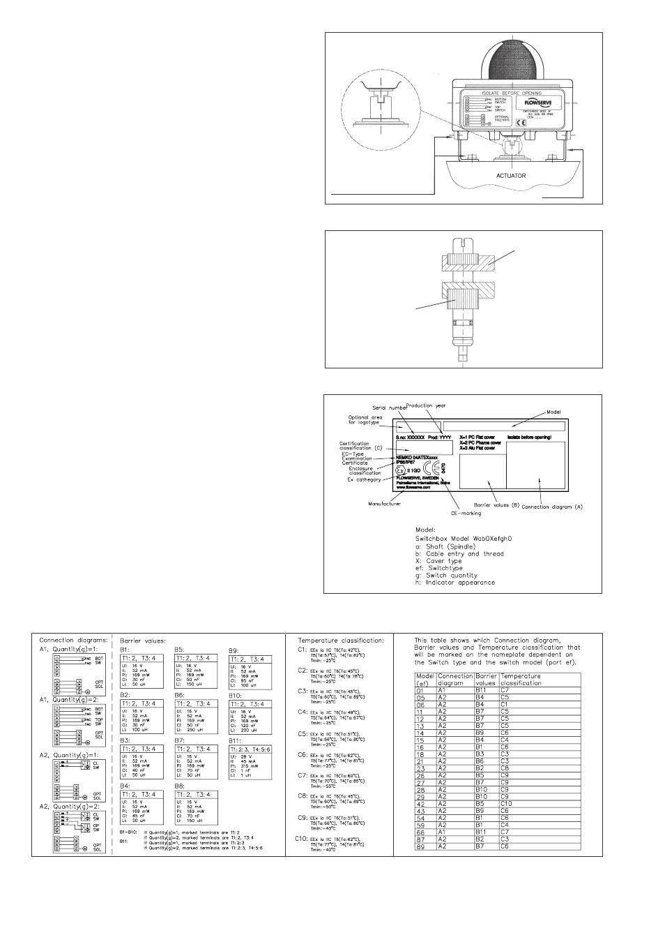
Connection diagrams — Certification info
Installation
Cam adjustment
Name plate
The information is subject to change without notice
Palmstierna International AB
Korta Gatan 9
SE-171 54 Solna, Sweden
Tel: +46 8 555 106 00
Fax: +46 8 555 106 01
www.pmv.nu [email protected]