Fig. 1: on-off actuator, air-to-open, 4flow control division – Flowserve 3 Series P6 Type Kämmer Pneumatic Actuator User Manual
Page 4
Advertising
4
Flow Control Division
Kammer Control Valves
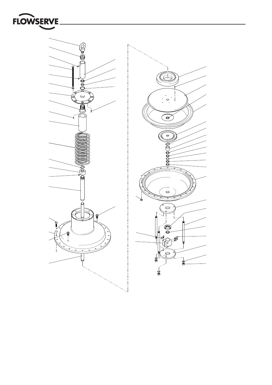
Fig. 1: On-Off actuator, Air-to-Open
1
Pre-tension plate
2
Grooved pin, Ø 5 x 25
3
Diaphragm plate
4
Diaphragm
5
Plate
6
Split ring
7
Ring
8
Ring
9
Back-up ring
10
O-Ring
11
Bushing
12
Diaphragm housing
13
Yoke plate, top
14
Slotted nut
15
Yoke rod
16
Wiper ring
17
Screw, NAMUR
18
Yoke plate, lower
19
Spring washer, M16
20
Nut, M16
21
Coupling, kpl.
22
Travel indicator, assy.
23
Nut, M12
24
Actuator stem
26
Screw, M12 x 50
25
Spring housing
27
Vent plug
28
Sleeve
1
2
3
10
4
5
6
7
8
9
10
9
11
12
13
14
15
16
17
18
19
20
23
22
21
27
26
25
27
24
6
30
29
28
42
41
40
38
36
35
34
33
32
31
39
16
11
37
2
29
Screw, M5 x 10
30
Nut
31
Spring guide
32
Grooved pin, Ø 6 x 16
33
Guide bushing
34
Plate
35
Washer
36
Screw, M6 x 10
37
Snap ring
38
screw
39
Cap
40
Grooved pin, Ø 5 x 25
41
Threaded insert
42
Eyebolt
43
Spring
43
Advertising