Flowserve CW41 Control Valves User Manual
Gestra steam systems, Product range a4
Description
The cooling-water control valves type CW are direct-acting
proportional controllers for installation in cooling water or
brine return lines. They ensure that the cooling-water outlet
temperature is maintained at a preset value, calculated for
the process requirements.
When using cooling-water control valves, higher tem-
peratures are possible than with an uncontrolled process.
As a result of the larger heat absorption by the cooling-
water or brine, cooling-agent and energy consumption
are reduced.
The regulator of the CW 41 consists of one, two or three
thermostats
3 (depending on the valve size) mounted in series
within a double-seat valve cone
2. The upper cone closes
tight whilst the lower one is designed with a tolerance
to form a leak passage (“s” cone), or the leak passage is
formed by a borehole in the cone (“r” cone).
The thermostats
3 contain an elastomer thermal expansion
material (“n” and “k” thermostats) or wax (“w” thermostat).
Under the influence of heat the volume of the thermostats
increases, projecting a pin which is included in the
thermostat body.
The lift of the thermostats is transmitted to the valve cone
via the pin of setting device
6, supporting the thermostats.
With rising cooling-water outlet temperature, the valve
cone is moved in the opening direction against the force
of the spring. When the temperature drops again the valve
cone is moved by the spring
7.1 in the closing direction.
With the aid of setting key
11 that can be removed and fits
all valve sizes, the position of the setting pin can be varied
to obtain higher or lower cooling-water outlet temperatures
(see “Temperature Adjustment”).
Even if the valve is closed, a continuous bleed flow ensures
a sensitive response. The bleed flow can be increased by
screwing setting screw
7.6 to the right (e.g. in the case of
a long line between heat exchanger and CW).
Installation
1. Screw pressure gauge (item 15) into the inlet (point A
in figure opposite) and thermometer (item 16) into the
outlet (point B in figure opposite). To avoid damaging
these instruments tighten them only at the hexagon
using a spanner (A.F. 14 and 19 mm).
2. Always install CW 41 in the cooling-water return line as
close as possible to the heat exchanger. Flow is in the
direction of arrow. Recommended position: in horizontal
lines, setting device
6 pointing downwards.
With free drainage the CW should be installed so that
it will not run empty, so as to prevent the formation of
deposits. If there is the danger of freezing it might be
useful to provide a drain valve in the water pocket (see
schematic diagram below). If necessary, the valve can
be emptied by unscrewing setting device
6.
Note: When the CW valve is closed, the cooling zone is
under full pump pressure.
Temperature ratings see “Adjustment Table”, page 4.
Differential pressure =
inlet pressure minus outlet
pressure.
Maintenance
The CW 41 does not require any particular maintenance.
If there is the danger of freezing, the valve should be
emptied.
Max. service pressure
16 barg (230 psig)
Max. differential pressure
6 bar (85 psi)
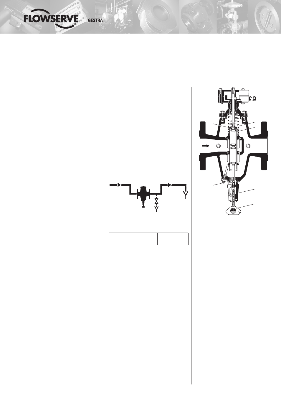
Pressure / Temperature Rating
A
= Connection for pressure gauge
B
= Connection for thermometer
CW 41 DN 40, 50
R ¼"
Setting pin
R ¼"
A
B
7.1
3
6
11
7.6
2
Instructions for Installation and Maintenance
Cooling-Water Control Valves Gestramat
CW 41, CW 41/4
PN 16, DN 25 – 100 mm (1 – 4")
Issue Date: 10/06
Product Range A4
GESTRA Steam Systems
CW 41
CW 41/4