Flowserve E325 User Manual
Installation, Stem packing adjustment, Seal replacement
McCANNA/MARPAC Valves
MMAIM2003
Tri-Pac Three-Piece In-line Maintainable Ball Valves
Models E325/E525
Installation, Operation and Maintenance Instructions
1. Installation
These valves may be installed in any position
utilizing normal pipe fitting practices.
Socket-Weld End Valves
To keep from destroying soft parts of the
valve, loosen two bolts and remove six bolts
as shown in Figures 1A, 1B, and 1C and
swing out the body as for servicing. Take care
that the end seals are not damaged. Note that,
for the FIRE-GARD
®
valves with socket weld
ends, extra end seals are included with the
valve. Seals are to be replaced during the
reassembly after welding. Prior to removing
the bolts to allow the body to swing out, the
valve may be tack welded in the line to
facilitate line-up.
The base material of valve covered by this
procedure conforms to the following:
• Carbon Steel - ASTM A105 (Forged)
• 316 Stainless Steel - ASTM A182
• GRF316 (Forged)
Before welding, push pipe snugly into end
adapters and then back off approximately
1
/
16
". The socket and at least one inch of the
pipe (at the joint) must be free of all foreign
material which might prove detrimental to
the weld.
Use the smallest electrode and minimum
amperage consistent with efficient welding to
minimize warpage. Tacks should be ground
out before completing the root pass in that
area. Weld stringer beads with no weaving
and stagger all starts and stops.
Carbon steel ends should be allowed to cool
slowly. The valve ends may be covered with a
welding blanket to promote slow cooling.
2. Stem Packing
Adjustment
If leakage is evident in stem packing area,
tighten the adjusting nut (7)
1
/
8
turn. If leak
still persists, repeat above.
Replacement of the stem seals (5) is indicated
if leak is still apparent.
3. Seal Replacement
a
WARNING: Begin with the valve partially
open in a depressurized line. Valve should
be cycled once to ensure there is no media
trapped behind the ball.
A. Turn ball (3) to open position and remove
handle nut (9), handle (8), adjusting nut (7),
travel stop (13), (part of the handle on sizes
1
/
4
" –
3
/
4
") and gland ring (6).
B. Loosen two bolts (14) (one per side in line
with each other) and remove remaining six
bolts (Figures 1A and 1B). The center body
section of the valve will swing out (Figure 1C)
for access to the ball (3), stem (4), seats (10)
and body seals (11).
NOTE: Valve must be in open position in
order to swing out body section.
C. Remove body seals (11) by using a sharp
instrument such as pocket knife. Care should
be taken to avoid damage to the surfaces of
the seal groove.
D. To take out one seat (10) and the ball (3),
rotate the stem (4) so ball (3) is in fully
closed position and insert wooden dowel (not
metal) in port and tap gently on ball (3)
thereby forcing it out of body (1).
NOTE: Extreme caution should be taken to
avoid damage to the ball (3).
E. Take out other seat (10).
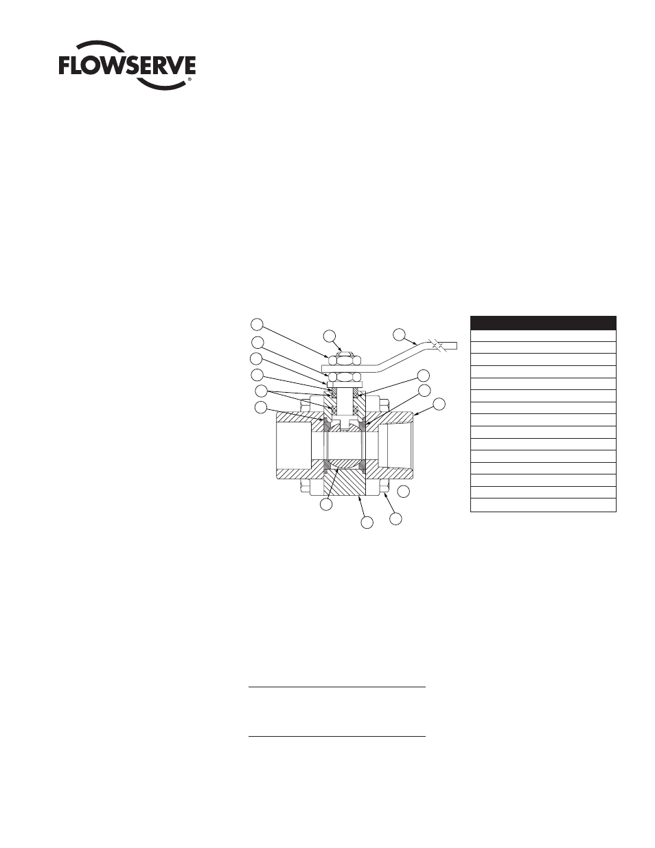
13
9
4
14
2
10
8
1
3
11
5
6
7
12
15
NOT
SHOWN
Part No.
Description
1
Body
2
End Adapters
3
Ball
4
Stem
5
Stem Seal Set
6
Gland Ring
7
Adjusting Nut
8
Handle
9
Handle Nut
10
Seat
11
Body Seals
12
Stop Pins (not shown)
13
Travel Stop
14
Bolts
15
Grounding Washer