Flowserve E790 User Manual
Petro double union end ball valve, Model e790, Installation
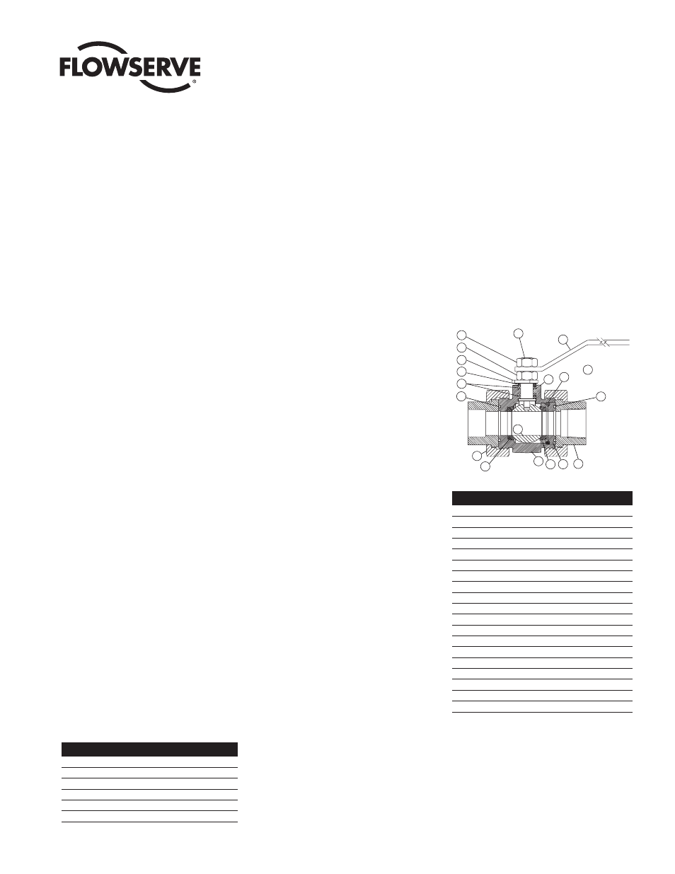
Figure 1
McCANNA/MARPAC Valves
MMAIM2002
(Part IM005)
Petro Double Union End Ball Valve
Model E790:
1
/
4
" – 2" Size
Installation, Operation and Maintenance Instructions
14
13
7
16
8
1
15
3
19
10
2
11
12
17
6
5
18
4
9
NOT
SHOWN
No.
Description
1
Handle
2
Stem
3
Stop Pin (not shown)
4
Handle Retainer Nut
5
Travel Stop (1" thru 2" sizes only)
6
Gland Ring
7
Threaded Spacer
8
Seat Socket
9
Ball
10
Seat (2)
11
Body Seal
12
Union Nut (2)
13
Union End (2)
14
Body
15
End Seal
16
Spacer Seal
17
Stem Seal
18
Adjusting Nut
19
Grounding Washer
Valve Size
Hex Size (Across Flats)
1
/
4
",
3
/
8
",
1
/
2
"
5
/
8
"
3
/
4
"
13
/
16
"
1"
1"
1
1
/
4
"
1
1
/
4
"
1
1
/
2
"
1
1
/
2
"
2"
1
11
/
16
"
down through the body and out the open
end of the body (14). Remove the upper
and lower stem seals (17) and the
grounding washer (19). Grounding wash-
er (19) is not used with the FIRE-GARD
valves. Save the grounding washer (19)
for reassembly.
Figure 2
1. Installation
These valves may be installed in any position
utilizing standard pipe fitting practices. With
the ends installed, the body can be rotated
before tightening the union nuts.
Welding Ends (Socket Weld)
To keep from destroying soft parts, loosen
and slide away union nuts (12). Remove
valve from line, taking care that the end and
body seals (15 & 16) are not damaged, and
then weld socket ends in position.
NOTE: Prior to removing valve from line,
valve may be tack welded in line for line-up
purposes.
The base material of valve covered by this
procedure conforms to the following:
•
Carbon Steel - ASTM A105 (Forged)
•
316 Stainless Steel - ASTM A182
GRF316 (Forged)
Before welding, push pipe snugly into union
ends and then back off approximately
1
/
16
".
The socket and at least one inch of the pipe
(at the joint) must be free of all foreign mater-
ial which might prove detrimental to the weld.
Use the smallest electrode and minimum
amperage consistent with efficient welding to
minimize warpage. Tacks should be ground
out before completing the root pass in that
area. Weld stringer beads with no weaving
and stagger all starts and stops.
Carbon steel ends should be allowed to cool
slowly. The valve ends may be covered with a
heat resisting blanket to promote slow cooling.
2. Stem Seal Adjustment
If leakage is evident in stem packing area,
tighten the adjusting nut (18)
1
/
8
turn. If leak
still persists, repeat above. Replacement of
the stem seal (17) is indicated if the leak is
still apparent after
1
/
2
turn.
3. Seal Replacement
There must be no line pressure on the valve
at this time and ball should be partially open.
A. Loosen union nuts (12) and slide nuts out
of the way. Now the valve body (14) can
be removed from the line for servicing.
B. Remove end seal (15) and body seal
(11). This may be done with a sharp
instrument, such as a pocket knife. Care
should be taken to avoid damage to the
surfaces of the seal groove.
C. Remove threaded spacer (7) by using
“allen” type wrench or hexagonal bar.
(See Figure 1.)
D. To take out spacer seal (16), seat socket
(8), one seat (10) and the ball (9) –
rotate stem (2) so ball (9) is in fully
closed position and insert wooden dowel
(not metal) in port opposite threaded end
and tap gently on ball (9) thereby forcing
it out of body (14).
NOTE: Extreme caution should be taken
to avoid damage to the ball (9).
E. Take out other seat (10).
F. Remove the handle retainer nut (4), han-
dle (1), adjusting nut (18), travel stop (5)
(part of the handle on sizes
1
/
2
" and
3
/
4
")
and the gland ring (6). Push the stem (2)