D. rebuilding, Worcester controls – Flowserve E818 Series User Manual
Page 2
2
E818/828 Series Fugitive Emissions 150# and 300# Flanged 2" - 8" Two-Piece Ball Valves
WCAIM2057
Flow Control Division
Worcester Controls
D. REBUILDING
a
WARNING: BALL VALVES CAN TRAP PRESSURIZED FLUIDS IN
BALL CAVITY WHEN CLOSED
If the valve has been used to control hazardous media, it must be
decontaminated before disassembly. It is recommended that the
following steps be taken for safe removal and disassembly:
Relieve the line pressure. Operate the valve prior to attempting
removal from line.
Place valve in half-open position and flush the line to remove any
hazardous material from valve.
All persons involved in the removal and disassembly of the valve
should wear the proper protective clothing such as face shield,
gloves, apron, etc.
CAUTION: If the seats and seals installed differ from those
removed, the valve nameplate or stop must be replaced or
remarked to indicate the altered materials and ratings or valve
tagged to so indicate.
1. A standard repair kit may be ordered for the valve. Specify the
size, series, material of seats and body seal and R# (revision
number) of valve or for non-standard valves, the “P” number,
“T” number, “C” number, or similar number, as found on the
nameplate. Some series, such as AF and FZ have their own
repair kits, which are ordered by the prefix. (Use Series 818 or
828 designation.)
Examples:
2. Special handling and cleaning procedures are necessary for
oxygen and vacuum service valves. Refer to industry practices
when overhauling these units.
3. To Disassemble 2"-8" Two-Piece Valves:
a. Valve should be placed with the end connector (smaller body
section) uppermost and on a clean surface, the valve
preferably clamped or bolted down. To disassemble end
connector from body, remove body stud nuts from mid-flange.
b. Strike end connector with mallet and close the valve. The
mid-flange connection should break open. Repeat if not
successful at first try. The end connector should now be lifted
vertically from the body and placed on the clean surface with
mid-flange end uppermost.
c. With the valve still in the closed position, the ball may now be
lifted from the body cavity, and the seats and body seal are
now exposed in either body or end connector. These should
now be removed. Care must be taken to avoid scratching the
machined faces on which they make contact with valve body
and end connector.
d. Remove the handle assembly and stop (if any), gland bolts,
Belleville washers, gland plate and follower from the top of
the valve.
e. Push the stem down into the body cavity and remove.
f.
Remove the thrust bearing and stem packing from the body.
CAUTION: Use care to avoid scratching the surface of the
stem and packaging chamber.
4. Visual Inspection:
a. The ball and the surfaces against which the seats are installed
should be undamaged, clean and free of pit marks and scratches.
Light marring from the action of the ball against the seats is
normal and will not affect the operation of the valve. Flaws which
can be seen but barely detected with fingertips are acceptable.
b. The stem and body surfaces that the thrust bearing and stem
seal(s) contact, must be undamaged, clean and free of pit
marks and scratches.
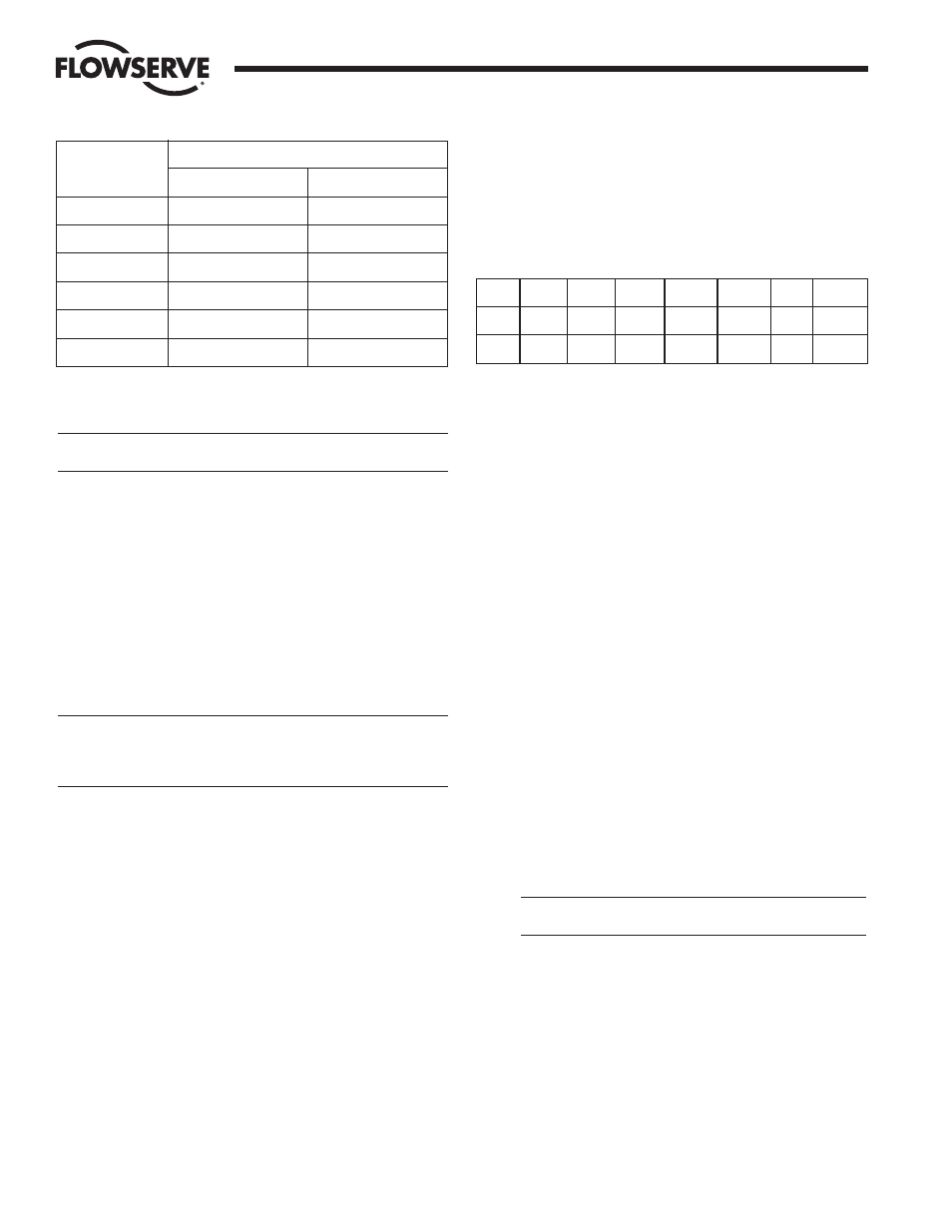
Gland Bolt Torque (In-Lbs)
Valve Size
“T” Packing
“G” Packing
2" E818/828
85 - 95
210 - 230
3" E818/828
175 - 200
270 - 295
4" E818
175 - 200
270 - 295
4" E828/6" E818
240 - 265
340 - 365
6" E828/8" E818
375 - 400
500 - 525
8" E828
950 - 1000
1450 - 1500
3"
E
AF
RK
818
TZ
R3
—
2"
E
RK
828
T
R3
—
4"
E
RK
818
RT
—
T0914
V
al
ve
S
iz
e
Fu
gi
ti
ve
E
m
is
si
on
D
es
ig
na
ti
on
P
re
fi
x
(i
f
re
qu
ir
ed
)
R
K
S
er
ie
s
M
at
er
ia
l
R
ev
is
io
n
N
o.
P,
T
,
C
o
r
si
m
il
ar
N
o.