Flowserve H71 Series User Manual
Worcester control valves, Installation, Operation
Worcester Control Valves
CAUTION: Flowserve recommends that all product that must be
stored prior to installation be stored indoors, in an environment
suitable for human occupancy. Do not store product in areas
where exposure to relative humidity above 85%, acid or alkali
fumes, radiation above normal background, ultraviolet light, or
temperatures above 120°F or below 40°F may occur. Do not
store within 50 feet of any source of ozone.
Worcester’s H71 valves will operate to 6000 psi at normal
ambient temperature (-40° to 185°F, -20° for carbon steel). If
used on liquid medias at these pressures, caution must be
practiced. Most liquid medias will flash or cavitate severely
when the pressure drop exceeds approximately 40% of the
system pressure. Severe valve and valve seat damage can
result.
Free discharge at these pressures is not recommended.
INSTALLATION
1. H71 valves may be installed for flow in either direction. Use care
to exclude pipe sealants from the valve cavity. Valves with
upstream relief hole in ball (V3 option) are one-way valves.
2. Weld End Valves:
NOTE: Prior to welding, THOROUGHLY CLEAN ALL JOINT SURFACES
to prevent contamination.
For all weld valves (SW, BW, End Connections):
a. Tack weld valve in place.
b. With valve open, remove all but one body bolt, loosen it and
swing out body. Close valve, remove ball, seats and body
seals. Return body to its original position and temporarily
secure it with two body bolts diagonally opposite each other.
c. Weld valve in line (when gas welding or brazing, do not play
flame on valve body).
d. Allow valve to cool, lubricate ball and seat with Lubriplate
930AA and reassemble valve.
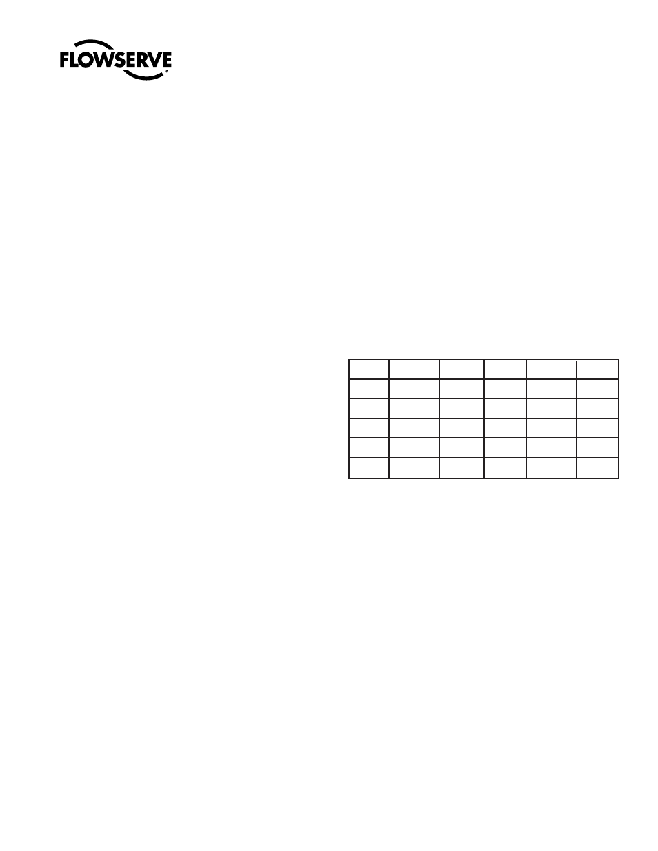
e. Tighten and torque body bolts evenly and diagonally opposite
each other, alternating in a criss-cross pattern. Use torque
figures shown.
CARBON STEEL
STAINLESS STEEL
BOLTS - B7
BOLTS - B8 CL2/2B
Bolt Dia.
In.-Lbs.
Ft.-Lbs.
Bolt Dia.
In.-Lbs.
Ft.-Lbs.
3/8"
480-540
40-45
3/8"
420-480
35-40
7/16"
680-720
55-60
7/16"
600-680
50-55
1/2"
984-1044
82-87
1/2"
960-984
80-82
5/8"
2100-2136
175-178
5/8"
1980-2040 165-170
3/4"
2940-3000
245-250
3/4"
2520-2580 210-215
NOTE: Stainless steel bolts and nuts are generally used in all three-
piece valves with stainless steel bodies.
f. Cycle the valve three times to break in the seats.
OPERATION
1. The operation consists of turning the handle and/or stem a
quarter-turn clockwise to close and a quarter-turn counter-
clockwise to open. When the handle and/or stem flats are in line
with the pipeline, the valve is open.
2. These valves will provide bubble-tight shut-off when used in
accordance with Worcester’s published pressure/temperature
chart.
3. It is not good practice to leave a ball valve partly open (throttling
operation) without knowledge of the pressure drop and flow at
that position.
4. As shipped from the factory, all valves may contain a silicone-
based lubricant (H71 valves also contain a lithium based grease).
This is for break-in purposes, and may be removed if it is
objectionable for a particular application by disassembling and
solvent washing. Lacquer thinner will remove the lubricant.
5. Media which can solidify, crystallize or polymerize should not be
allowed to stand in ball valve cavities.
14932-D
High Pressure Series H71
(C0214, C0222, C0224) Ball Valves
Installation, Operation and Maintenance Instructions