Maintenance – Flowserve SB Control Valves User Manual
Page 5
ShearStream SB
FCD VLENIM4152-01 07.09
5
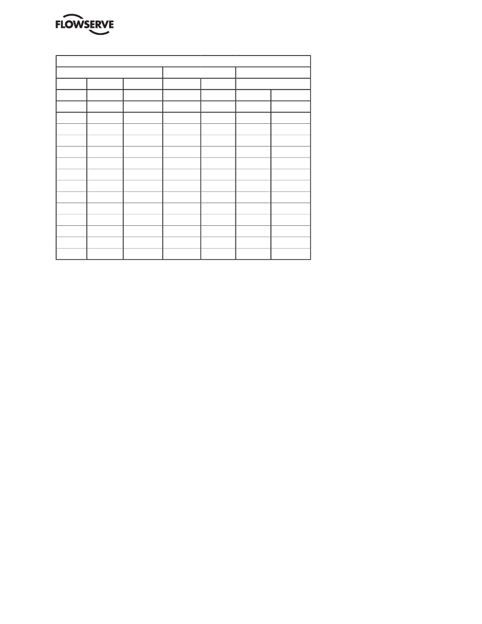
8. Product code for important spare parts and spare parts sets
8.1 Ordering of Spare Parts
When placing orders for spare parts, specify:
1. Product code of the valve - incl. DN, see part No.
specifi ed on the identifi cation plate of the valve.
2. Description of the part, its item No. or spare
parts set number, and the quantity required.
Ordering example
For ShearStream SB 8782EB-0200-AAAABA,
Part. No. 1234567
1 - Stem upper, item 3
or
For ShearStream SB 8782EB-0200-AAAABA,
Part. No. 1234567
1 - Stem sealing set, product code 349 08 052
9. Maintenance
If the ball segment or seat ring has sustained damage due
to impurities in the pipework or for some other reason, or
if the seat ring and stem seals need replacing after a long
period of service, the valve must be overhauled.
Many valves are installed in such locations that their
performance is of decisive importance to the entire
process. Such valves should be inspected regularly and
any faults should immediately be corrected.
9.1 To remove the valve from the pipework
The procedure for inspection and maintenance, for
which no special tools are necessary, is as follows:
1. Ensure that the recommended spare parts and
also the gaskets - important - for the pipe
fl anges are available.
2. Close the valve.
3. Shut off all compressed air connections
and isolate all electrical connections to the
actuator.
4. Disconnect all compressed air lines and electric
cables connected to the actuator.
5. Release the fl anged joint between the valve
and the pipework. Then lift out the valve. Don’t
use the actuator for lifting. Apply all lifting
forces to the valve itself and not to the actuator
- see fi g. 1.
Note the direction of fl ow which is shown by an
arrow on the valve body.
9.2 To inspect the ball sector and seat ring
1. If an actuator is fi tted to the valve, remove it. See
section 9.3, items 1 and 2.
2. Remove the indicating pin (23 - fi g. 4).
3. Turn the ball sector through more than 90°, until
it is no longer in contact with the seat ring.
4. Push the seat ring out of its seat at the valve
body inlet. Withdraw it past the ball sector -
between the ball sector and the inside
of the valve body - towards the outlet, and
remove it from the body.
* Three rings are requested per valve for DN 25 - 100, four rings per valve for DN 150 - 300
Set or detail
Stem sealing set
Seat ring set
Other spare parts
Type
Zebra CL ™
Safeguard
Alloy 6
PTFE
Item No
19A
19B
11, 12
12, 29
7
10
DN
25
349 08 050
349 25 540
349 08 080
349 17 460 348 88 295
333 98 460
0040
349 08 050
349 25 540
349 08 081
349 17 461 348 88 295
333 98 461
0050
349 08 050
349 25 540
349 08 082
349 17 462 348 88 295
333 98 462
0065
349 08 050
349 25 540
349 06 089
349 17 469 348 88 295
333 98 469
0080
349 08 050
349 25 540
349 08 083
349 17 463 348 88 294
333 98 463
0100
349 08 050
349 25 540
349 08 084
349 17 464 348 88 294
333 98 464
0150
349 08 051
349 25 500
349 08 085
349 17 465 348 88 290
333 98 465
0200
349 08 052
349 25 720
349 08 086
349 17 466 348 88 291
333 98 466
0250
349 08 053
349 25 760
349 08 087
349 17 467 348 88 292
333 98 467
0300
349 08 054
349 25 140
349 08 088
349 17 468 348 88 293
333 98 468
0350
-
349 25 180
349 17 430
349 20 030 349 15 260
333 00 430
0400
-
349 25 180
349 17 431
349 20 031 349 15 260
333 00 431
0500
-
349 25 180
349 17 432
349 20 032 349 15 261
333 00 432