Flowserve Valtek Mark Eight Control Valve User Manual
Valtek mark eight y-body valves
8-1
Valtek Part No. 49018
Valtek Mark Eight
Y-body Valves
GENERAL INFORMATION
The following instructions are designed to assist in
performing maintenance as required on Valtek
®
Mark
Eight control valves. Product users and maintenance
personnel should thoroughly review this bulletin in con-
junction with separate Flowserve Installation, Opera-
tion, Maintenance Instructions 1 (Mark One and Two
Control Valves) and 2 (Cylinder Actuators) before in-
stalling, operating, disassembling, or performing any
maintenance on the valve.
To avoid possible injury to personnel or damage
to valve components, WARNING and CAUTION
notes must be strictly adhered to.
Standard Valtek Mark Eight valves are identical to Valtek
Mark One valves with exception of the “Y-body” configu-
ration. On high temperature applications, Valtek Mark
Eight valves use a special seat retaining ring.
High Temperature Seat Ring Removal
Valtek Mark Eight valves used on high temperature
applications do not have a seat retainer. Instead, a spiral
retaining ring is used to hold the seat firmly in place.
Special tools for disassembly are included with the valve
shipment (if replacements are required, contact a local
Flowserve sales office). To disassemble these special
Valtek Mark Eight valves, refer to Figure 1 and proceed
as follows:
1. Disassemble the valve as outlined in Installation,
Operation, Maintenance Instructions 1.
WARNING: Drain all fluids from valve and depres-
surize line to atmospheric pressure. Failure to do
so can cause serious injury.
2. Insert the base plate (installation tool No. 1) under the
seat ring so that the tool engages the body (refer to
Figure 1).
3. Insert the top compression plate (installation tool
No. 2) into the seat ring.
CAUTION: Do this operation carefully, making
sure the seating surface is not galled or scored.
4. Bolt the two plates together using the supplied bolts.
5. Tighten until seat ring O-ring gasket is compressed.
NOTE: High bolt torque will be necessary to com-
press the O-ring.
6. Remove the seat ring retaining ring. The retaining
ring can be easily removed with a screwdriver in-
serted into the slot provided in the ring.
7. With the retaining ring removed, the assembly can
be unbolted and the seat ring and gasket may be
pulled out.
High Temperature Seat Ring Assembly
Refer to Figure 1 and proceed as follows:
1. Install new seat gasket and relocate seat ring. It is
necessary to replace all gaskets each time the valve
is disassembled.
2. Place the installation tools together as outlined in the
‘Removal’ section, applying enough pressure to
allow the retaining ring to be installed.
3. After the ring has been installed, remove the instal-
lation tools from the body.
4. Reassemble the valve according to Installation,
Operation, Maintenance Instructions 1.
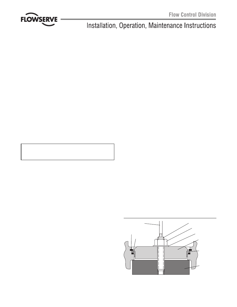
Figure 1: High Temperature Seat Ring
(NOTE: Item numbers correspond to the valve’s bill of material)
Assembly
Retaining Ring
(Item No. 30)
O-ring
(Item No. 55)
Stud
Nut
Washer
Tool No. 2
Seat Ring
(Item No. 20)
Tool No.1