Worcester controls – Flowserve 94 Series User Manual
Page 9
Advertising
06957-L
9
Flow Control Division
Worcester Controls
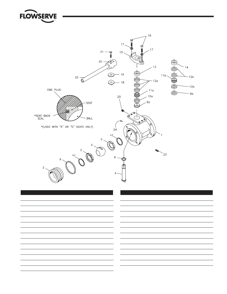
Part
Name
Qty
1
Body
1
2
End Plug
1
3
Ball
1
4
Stem
1
5
Seat
2
6
Body Seal
1
*7
Seat Back Seals (Metal Seats Only)
2
8
Thrust bearing
1
9a
Filler Ring
1
9b
Graphite Ring
1
10a
629 Seal
1
10b
Graphite Ring
1
11a
Lantern Ring T
1
11b
Lantern Ring G
1
12a
Chevron Ring
3
Part
Name
Qty
12b
Graphite Ring
2
13
Follower T
1
14
Follower G
1
15
Gland Plate
1
16
Gland Bolt
2
17
Belleville Washer
12
18
Stop
1
19
Spacer (not always present)
1
20
Wrench Block
1
21
Hex Head Bolt
1
22
Wrench Extension
1
23
End Plug Screw
4-8
24
Name Plate
1
25
1
/
8
" NPT Pipe Plug
1
Series 94-150 and 94-300
(3"–6" Flanged)
NOTE: Wrench assembly and stop are
optional and ordered separately.
Advertising
This manual is related to the following products: