Flowserve Mechanical Brake to 10-23 75 120 VAC Actuators User Manual
Installation, operation and maintenance, I. assembly
Mechanical Brake to 10-23 75
120 and 240 VAC Actuators
Installation, Operation and Maintenance
FCD WCAIM2072-00 (Part 16434)
I. Assembly
a
CAUTION: The actuator’s rated voltage must be the same
as the brake coil’s rated voltage as marked on the brake
coil housing.
1. Remove the actuator cover.
2. Mount the coil housing (2) parallel to the sides of the mount-
ing plate (1), using the two small pan head screws and their
Iockwashers. Locate the front edge of the coil housing onto the
brake mounting plate so that the coil housing lines up with the
two cast lines on the mounting plate. (See Figure 1.)
3. The mounting plate is preliminarily secured loosely by the
existing motor screws (4 screws) on the inner sides of motor
stators), as shown in Figure 1. For single motor actuators,
two spacers (7) and screws are provided to support the brake
mounting plate.
4. Insert the coil plunger (3) into the coil housing with the coil
plunger pin facing up.
5. Mount the brake arm (4), as shown in Figure 1, so that the
middle hole of the arm fits over the taller mounting plate post
and the end hole in the arm fits over the coil plunger pin.
6. Install the retaining clip over the brake arm post using a tool
similar to a nut driver. DO NOT force the retaining clip onto the
post so that the brake arm binds. Once the clip is in position, the
brake arm must be able to move freely in either direction, with
no binding.
7. Install the set screws into the brake disc(s) (5). Place disc over
the motor shaft, align it with brake arm pad, and secure set
screws. Be sure that the brake disc fits securely onto the motor
shaft extension.
NOTE: Actuator sizes 20-23 use two brake discs and one brake
arm, as shown in Figure 1. The second brake disc acts as a fan
to cool the motor.
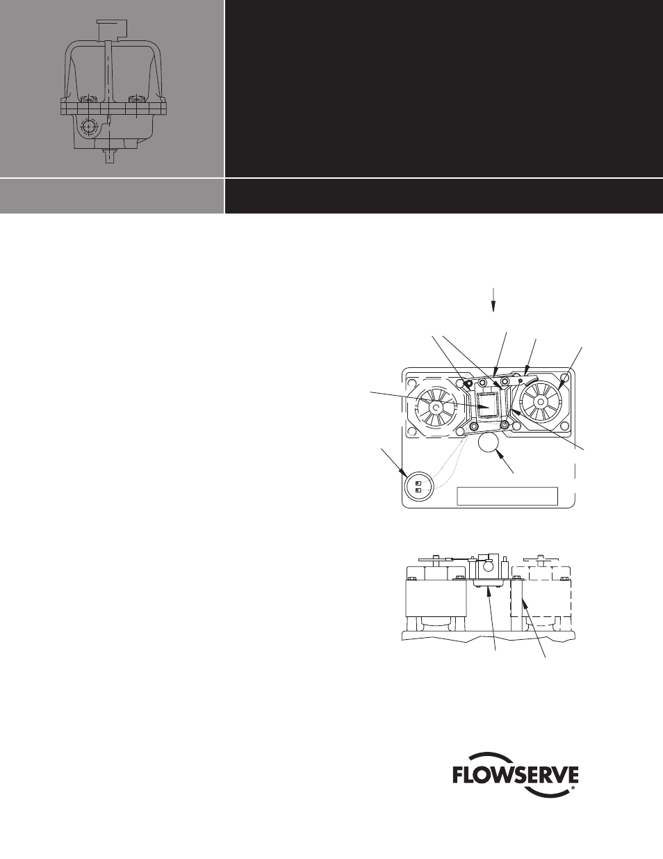
Figure 1 – Size 1023 75 120 VAC
VIEW A
7
1
VIEW A
5
6
4
3
2
ACTUATOR
SHAFT
TERMINAL STRIP
CAPACITOR
MARK ON
MOUNTING
PLATE
���������������������������