Flowserve CLC Module 10-30 75 Actuator User Manual
Installation, operation and maintenance, Installation and adjustment
CLC Module
10-30 75 Actuator
Installation, Operation and Maintenance
FCD WCAIM2071-00 (Part 15516)
a
CAUTION: CLC module must be used with proper
line voltage.
Remove the mounting screws from the right-hand limit switch(es)
(viewed from terminal strip). Place the spacers and CLC module on
top of the limit switch(es) with the nameplate up. Fasten in place
with the longer mounting screws and wire provided, following the
desired schematic.
Control of the actuator’s cycle time is achieved by breaking up the
power applied to the actuator into a series of pulses.
The length of time a power pulse is applied is controlled by the “ON”
adjustable control.
The interval between pulses is controlled by the “OFF” adjustable
control.
To adjust, start with both controls at midpoint.
To reduce cycle time on 120 VAC units, turn “ON” control in clock-
wise direction and “OFF” control in counterclockwise direction.
To increase cycle time, turn “ON” control in counterclockwise
direction and “OFF” in control clockwise direction.
To reduce cycle time on 240 VAC units, turn “ON” control in
counterclockwise direction and “OFF” control in clockwise direction.
To increase cycle time, turn “ON” control in clockwise direction and
“OFF” in counterclockwise direction.
IMPORTANT: If “ON” time adjustable control is at minimum and/or
“OFF” time adjustable control is at maximum, the actuator will not
rotate. The minimum “ON” pulse must allow the actuator to move a
closed valve out of its seat. Verify proper CLC operation by opening
a fully closed valve.
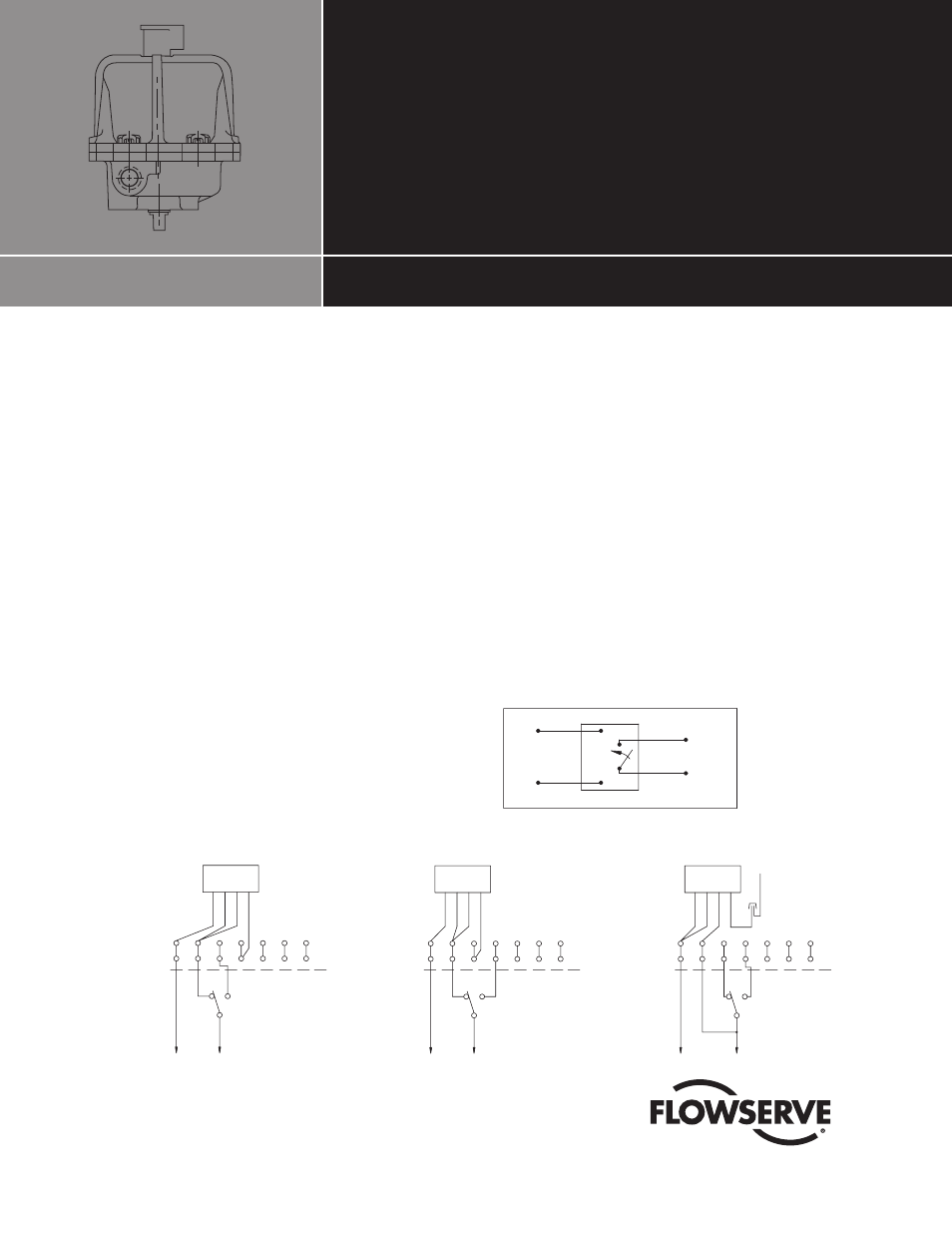
Wiring Diagrams – 10–30 Series 75 Actuators
WHITE
N.O.
RED
INPUT
BLACK
BROWN
CONTACT
CLC
PULSE CW
7
6
RE
D
BLACK
4
3
5
AC HOT
2
1
TERMINALS
ACTUATOR
NEUT.
WHITE
BROWN
OR CLOSE
7
CLC
6
5
BLACK
RE
D
4
3
2
AC HOT
WHITE
1
ACTUATOR
TERMINALS
NEUT.
BROWN
OR OPEN
PULSE CCW
CLC
PULSE CW & CCW
7
6
5
BLACK
RE
D
3
2
4
AC HOT
WHITE
1
TERMINALS
ACTUATOR
NEUT.
& CLOSE
WHITE TO MOTOR
BROWN
OR BOTH OPEN
General Schematic
Customer Wiring
Customer Wiring
Customer Wiring
Installation and Adjustment
Wiring Diagrams – 10–30 Series 75 Actuators
WHITE
N.O.
RED
INPUT
BLACK
BROWN
CONTACT
CLC
PULSE CW
7
6
RE
D
BLACK
4
3
5
AC HOT
2
1
TERMINALS
ACTUATOR
NEUT.
WHITE
BROWN
OR CLOSE
7
CLC
6
5
BLACK
RE
D
4
3
2
AC HOT
WHITE
1
ACTUATOR
TERMINALS
NEUT.
BROWN
OR OPEN
PULSE CCW
CLC
PULSE CW & CCW
7
6
5
BLACK
RE
D
3
2
4
AC HOT
WHITE
1
TERMINALS
ACTUATOR
NEUT.
& CLOSE
WHITE TO MOTOR
BROWN
OR BOTH OPEN
General Schematic
Customer Wiring
Customer Wiring
Customer Wiring
All wiring to terminal strip should be inserted only to midpoint of terminal strip.
���������������������������