Maintenance, Disassembly, Reassembly – Flowserve Handwheels and Limit Stop User Manual
Page 12: Figure 7: pull-only limit stop
5-12
Flowserve Corporation, Valtek Control Products, Tel. USA 801 489 8611
O
C
3. Readjust the jam nuts until they are seated next to
the limit stop flange. Tighten jam nuts securely
against each other.
Maintenance
For proper maintenance, maintain a coat of multi-
purpose lubricant on the limit stop bolt threads at all
times. To do this:
1. Apply air under the piston until the actuator is fully
retracted, exposing the bolt threads.
2. Remove the limit stop jam nuts.
3. Clean and lubricate the threads.
4. Return limit stop jam nuts to the desired position.
5. Securely tighten the jam nuts against each other.
Disassembly
Refer to figure 7:
WARNING: Repressurize the line and actuator to
atmospheric pressure before disassembling the
limit stop or removing the actuator from the valve,
or serious personal injury could result.
1. The limit stop may be disassembled while mounted
on the valve, or the actuator can be removed and
disassembled separately (see the valve’s mainte-
nance bulletin for instructions).
2. Vent air on both sides of the piston.
3. Loosen and remove the limit stop jam nuts.
WARNING: Cylinder is spring loaded. Do not
attempt to remove the flange bolts without fol-
lowing Steps 4 and 5 exactly or serious injury
could occur.
4. Remove all but two opposing flange bolts and bolt
gaskets.
5. Remove the two remaining bolts slowly and simul-
taneously, relieving the remaining spring compres-
sion. The bolts are of sufficient length to relieve all
spring compression prior to releasing the flange.
6. Lift the limit stop flange off the cylinder, taking care
not to damage the limit stop bolt threads and
bushing. Remove flange gasket from top of cylin-
der.
7. Remove the limit stop flange O-ring.
8. The actuator may now be disassembled according
to Maintenance Bulletin 2.
9. Unless the limit stop bolt is to be replaced, do not
remove the pin from the actuator stem, since re-
aligning the pin hole in both pieces is difficult.
However, if it is necessary to replace the piston
stem O-ring, drive the stem pin out and screw the
limit stop bolt off the actuator stem.
Reassembly
Refer to Figure 7:
1. Make sure all internal parts are thoroughly cleaned
and lubricated before beginning reassembly. Use
only new O-rings and gaskets (O-rings should be
lubricated with a silicone lubricant such as Dow
Corning 55 M).
2. Reassemble the actuator according to Maintenance
Bulletin 2. If the limit stop bolt is being replaced,
replace the piston stem O-ring and screw the limit
stop bolt and the actuator stem together. Realign
the pin hole and drive the stem pin firmly in place.
Reassemble the cylinder and retaining ring accord-
ing to Maintenance Bulletin 2.
3. Replace the limit stop flange O-ring. Install the
flange and a new flange gasket on the cylinder.
4. Using new bolt gaskets, install two opposing bolts-
and tighten evenly to compress the spring.
5. Reassemble the four remaining bolts and bolt gas-
kets. Tighten sufficiently to form a proper seal with
the flange gasket and bolt gasket.
6. Apply air under the piston until the desired limit
position is reached.
7. Reinstall the limit stop jam nuts until they are seated
against the limit stop flange. Tighten both jam nuts
firmly against each other.
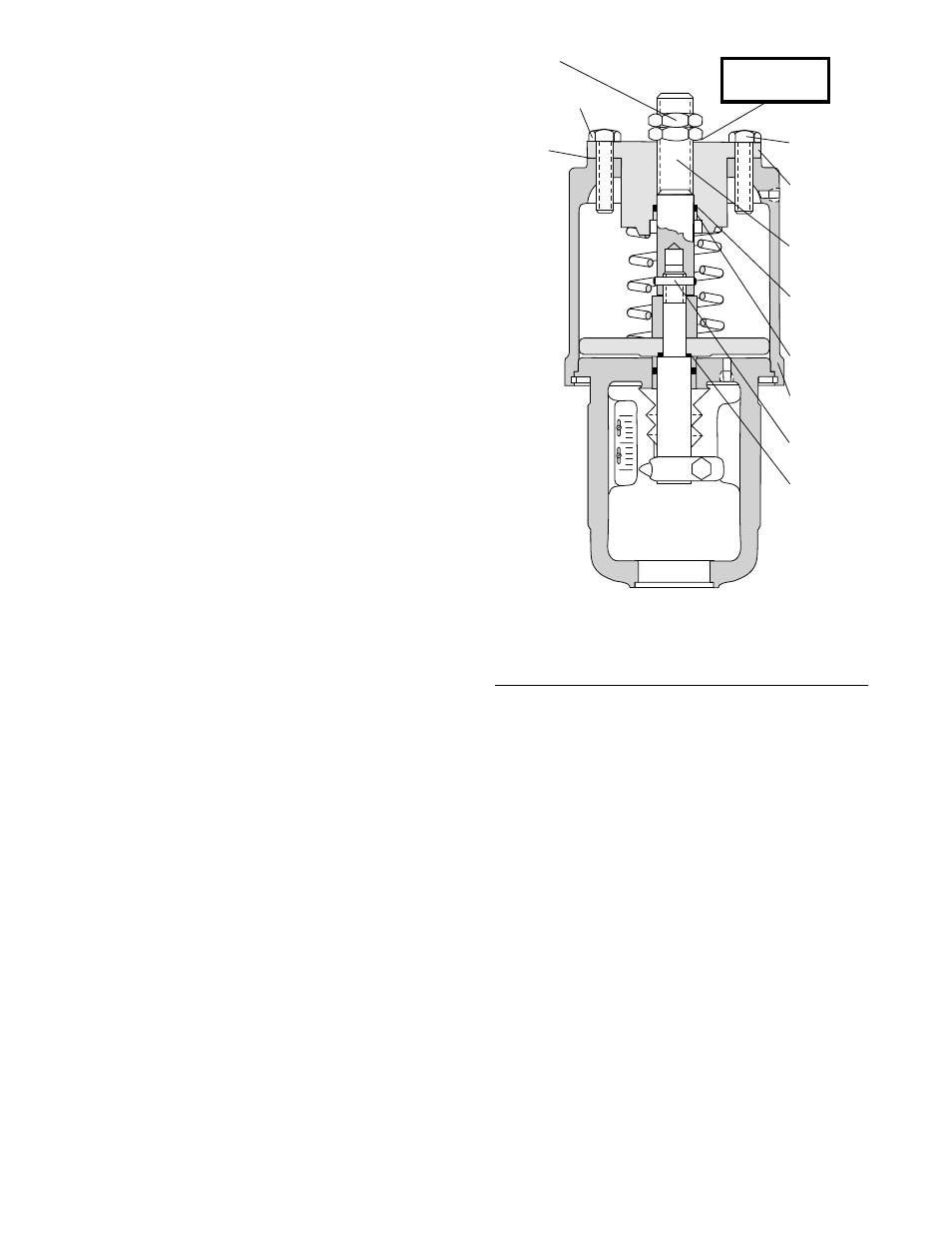
Figure 7: Pull-only Limit Stop
NOTE: Item numbers shown above correspond directly to the valve’s
bill of material. Refer to the bill of material or specific part numbers.
Jam Nut
(Item No. 350)
Bolt Gasket
(Item No. 379)
Flange
Gasket
(Item No. 378)
Flange Bolts
(Item No. 333)
Limit Stop
Flange
(Item No. 389)
Limit Stop Bolt
(Item No. 380)
Limit Stop
Flange O-ring
(Item No. 276)
Bushing
(Item No. 390)
Cylinder
(Item No. 202)
Pin
(Item No. 372)
Piston Stem
O-ring
(Item NO. 272)
WARNING:
MOVING PARTS!
KEEP HANDS CLEAR