Supernova series, Pag e, Rack & pinion automax actuators – Flowserve SuperNova Series User Manual
Page 3
SuperNova Series
S050
− S200
Rack & Pinion AUTOMAX Actuators
Pag
e
B00043e4-rev
3.doc
3/4
MAINTENANCE INSTRUCTIONS
Disassembly Procedures
1. Disconnect all air and electrical supplies from actuator.
2. Remove all accessories from actuator and dismount
actuator from valve.
3. Position actuator with air supply ports facing you. Apply
air pressure to Port 2 to release spring pressure from the
Stop Bolt (9).
4. Remove the Stop Bolt Retaining Nut (14), Washer (15),
and O-ring (16) on the left Endcap (19) and turn the Stop
Bolt (9) clockwise into the Body (1) until it is flush with
the Endcap (19).
5. Exhaust air from Port 2, the Stop Bolt (9) should now
turn freely. Continue turning Stop Bolt (9) clockwise until
it is disengaged from the Endcap.
6.
S Spring Return Actuator:
CAUTION: Follow step 4 to relieve force on inward travel
stop before proceeding.
To remove S Endcaps, first completely remove two
diagonal Endcap Screws (21) from one Endcap. The two
remaining Encap Screws should be removed evenly. As
the screws are removed, the springs will push the
Endcap out. Repeat for opposite side. The springs well
be totally unloaded before the screws are completely
unthreaded.
Remove the springs (23, 24, 25).
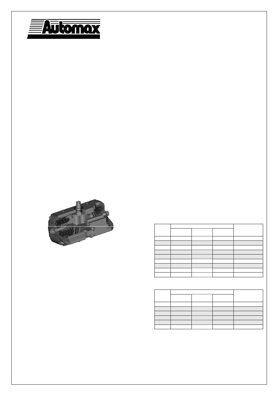
Spring return version
D Double Acting Actuator:
Remove the 8 Endcap Screws (21). Step 7 will push the
Endcaps (18, 19) from the Body (1).
7. Rotate Pinion (3) counterclockwise (D & S-FCW) or
clockwise (D & S-FCCW) to drive the Pistons (2) off the
end of the rack. Pull the Left Piston (2) from the body (1)
by pulling on the Stop Bolt (9).
8. Remove the Right Piston (2a) by pushing out through
inside of Body (1).
9. Remove the Snap Ring (5) Steel Pinion Washer (4a) and
Pinion Washer (4).
10. Tap Pinion (3) lightly with plastic mallet to remove.
11. Remove seals from pinion, endcaps, and piston. If
necessary, remove seal from top pinion bearing.
12. Top pinion bearing (26) is a light press fit into the
housing. To remove, press out towards the bottom of the
actuator body. Take care not to damage any of the
surfaces. Bottom pinion bearing (27) is split. To remove,
find split in bearing and spread apart just enough to fit
over bottom pinion.
Reassembly Procedures
1. Inspect all parts for wear and replace any worn parts as
needed. Replace all O-rings.
2. Clean all components and lightly grease cylinder bore,
pinion and seals with a multi-purpose “polymer” fortified
grease such as DuBois Chemicals MPG-2.
3. Reverse the disassembly procedures to reassemble.
4. If top pinion bearing (26) was removed, it must be
pressed back into place. The top edge of the bearing
must be even with the top of the body. Insert top pinion
bearing seal (28) into place, pressing down with a blunt
screwdriver or similar tool, taking acre not to damage the
seals.
5. The standard Pinion (3) orientation is with the top
accessory drive slot at 90° to the Body (1) in the 0°
position.
6. When fitting the Pistons (2 and 2a) ensure the teeth
engage the Pinion (3) at the same time by measuring in
from each end. Note: the orientation of the pistons will
determine the operation of the actuator. Refer to the
diagrams under “Operation” for correct piston position.
7. Test the actuator for smooth operation and air leakage at
service pressure before reinstalling.
Changing Number of Springs
1. Follow the Disassembly Procedures through step 6
2. Determine nested spring combination of inner, middle
and outer spring. Consult catalog torque charts. Insert
appropriate spring according to the attached chart into
cylinder. Springs must be properly seated against
piston and endcap to assure that springs do not bind.
3. Re-assemble
the
actuator.
Spring chart models 63-200
Spring Combination 1
Spring
Group
#1 Spring
(inner)
#2 Spring
(middle)
#3 Spring
(outer)
Standard
Configuration
(Air Supply)
S04
- 2 -
S05
-
1
1
3 bar
S06
- - 2
S07
1
-
2
4 bar
S08
2
-
2
5 bar
S09
1 1 2
S10
-
2
2
5,5 bar
S11
1 2 2
S12
2 2 2
Spring chart model 50
Spring Combination 1
Spring
Group
#1 Spring
(inner)
#2 Spring
(middle)
#3 Spring
(outer)
Standard
Configuration
(Air Supply)
S04
1 1 -
S05
-
2
-
3 bar
S06
2
1
-
4 bar
S07
1
2
-
5 bar
S08
2
2
-
5,5 bar
S09
2 - 2
Notes:
#1 Spring has one color code dot
#2 Spring has two color code dots
#3 Spring has three color code dots
S050 has maximum of 2 springs per endcap