Flowserve Lockout Module User Manual
Lockout module, Installation instructions, Operation
Installation Instructions
The Automax ISO pattern Lockout Modules (LOM)
allow simple mechanical lockout of new and existing
valve/actuator assemblies. Six models of the Lockout
Module mount directly to any ISO pattern actuator with
F05 through F16 patterns. The Lockout Module
provides a compact mechanical lockout assembly
which when properly implemented will satisfy OSHA
Standard 1910.47, " The Control of Hazardous
Energy". The Lockout Module mounts directly
between a standard valve mounting kit and an ISO
pattern actuator, requiring only a special coupler for the
specific valve/actuator combination. This allows for
easy field retrofit of a mechanical lockout device to
existing valve/actuator assemblies.
To install:
1. Note valve position, open or close. Move valve to
desired lockout position. The actuator should be
in a corresponding position.
2. Mount standard valve mounting kit to valve.
3. Install Lockout coupler to valve stem, properly
orienting coupler for desired actuator position.
4. Position Lockout Module as desired on top of
mounting kit. Insert lockout pin through lockout
coupler to properly orient the lockout module.
Tighten bolts until snug.
5. Place actuator onto lockout module. Tighten bolts
until snug.
6. Stroke actuator several times to properly align
coupler. If necessary, adjust actuator travel stops
at this time.
7. Return valve to desired lockout position. Insert
lockout pin through lockout coupler to ensure
proper alignment. If necessary, loosen
bracket/LOM bolts and rotate LOM to align lockout
coupler with LOM slots to allow pin insertion.
Tighten all mounting hardware.
8. Remove lockout pin from coupler and insert into
storage brackets in the side of the LOM housing.
9. Stroke actuator several times to ensure mounting
bolts are tight enough. Lockout module should not
slip in actuator or bracket.
Operation
The Lockout pin may be stored and locked in the
storage brackets provided on the Lockout housing.
To lock out a valve, position valve in desired setting.
The hole in the Lockout coupler should align with the
slots in the Lockout housing. Insert the Lockout pin
through the hole in the Lockout coupler, and apply a
B00160-0
1
Page 1 0f 2
11444 Deerfield Road
Cincinnati, Ohio 45242
(513) 489-7800
FAX (513) 489-5243
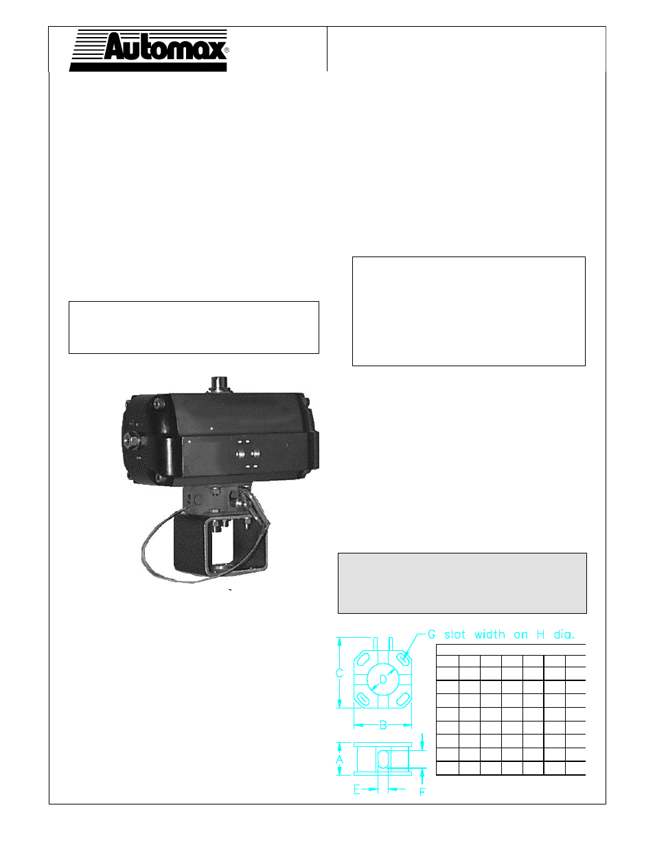
Lockout Module
ISO Pattern
ISO Pattern Actuator
Lockout
Module
Tethered
Lockout
Pin
Standard
Mounting Kit
Installation, Operating, and Maintenance Instructions
Note: The Automax Lockout Module is not suitable
for valves requiring a constant positive shut-off
torque to ensure sealing.
Note: When locking out a high-performance
butterfly valve, or other valves with "quick
opening" characteristics, bias the lockout
module housing against the lockout pin. To
lockout a HPBV in the closed position, rotate
housing clockwise against pin to keep valve
from opening counter clockwise.
A 1.69 1.63
2.00 2.13
2.50 2.75
B 2.06 2.82 3.95 4.91 5.63 6.65
C 2.61 3.41 4.95
6.00 6.76 7.89
D
1.1 1.56 2.52 2.9 3.2 3.94
E
*
0.53
0.53
0.66
0.78
0.78 1.03
F
*
0.86
0.86 1.12 1.25 1.25 1.5
G 0.28 0.34 0.41 0.53 0.66 0.78
H 1.97 2.76 4.02 4.92 5.51 6.5
Warning: Do not stick foreign objects, such as
fingers, screwdrivers etc. into Lockout hole.
Serious injury may result. Use only Lockout pin
supplied with Lockout Module to lock out actuator.
* (4) places centered on housing