Air supply and electrical installation, Worcester controls – Flowserve 10 ACCESS I 39 Actuator with AS Interface User Manual
Page 3
WCAIM2041
10, 15, 20 Access I 39 Acutators with AS Interface
3
c. To change indication, push out (remove) red and white
buttons and reassemble in opposite positions.
d. Locate indicator on actuator shaft flats. Press firmly until
location nibs snap into recess on actuator shaft.
AIR SUPPLY AND ELECTRICAL
INSTALLATION
A. 1. Air Supply
The Series 39 Actuator is factory lubricated. For optimum
operation, the use of filtered and lubricated air is
recommended.
2. Air Supply Pressure
Standard double-acting actuators require 40-120 psig supply
air. Spring return actuators require 80-120 psig supply air.
Spring-return actuators can also be set up to operate on
supply air pressures ranging from 40-80 psig by using fewer
springs. See “Rebuilding Instructions”, Spring-Return
Actuator, paragraph 1 on page 9 for proper number and
location of springs for reduced supply air pressures.
3. Air Supply Connection
Connect air supply to
1
/
4
" NPT connection on control block.
4. Recommended Tubing Sizes
In order to provide sufficient flow of supply air to the Series
39 actuator, the following tubing sizes are recommended:
Actuator
Runs Up To
Runs Over
Size
4 Ft. Long
4 Ft. Long
10, 15, 20
1
/
8
"
1
/
4
"
5. Air
Consumption
The following chart shows the amount of pressurized (80
psig) air consumed per stroke in cubic feet. To determine the
total amount of air consumed per complete cycle for double-
acting actuators, simply add the volumes for both the
opening and closing strokes together; for spring-return units,
the total volume of air consumed is the volume shown for
the opening stroke.
Actuator Size
Stroke
1039
1539
2039
Open
.04
.08
.16
Close
.05
.09
.17
6. Electrical
Supply
Make electrical connections in accordance with the wiring
diagram on the inside of cover or appropriate wiring diagram
in Section C.4.
The power supply to the solenoid coil is 3 watts. Required
amperage is as follows:
Voltage
Holding Amps
24 VDC
.13
7. Switch (Sensor) Ratings:
Mechanical Switch – 15.1 amps at 125/250 VAC;
.5 amps at 125 VDC.
NAMUR Proximity Sensor – ≤1 mA (target present), ≥3 mA
(target absent) 15 mA max., 5-25 VDC, sensing range 2 mm,
switching frequency 1 KHz. Not sensitive to polarity.
B. Circuit Board Specifications
1. ID and IO Codes:
ID = F
IO = D
D0 = Energize solenoid (Bit 0)
D1 = LB/SC monitoring of the solenoid output (Bit 1)
D2 = CW Switch/Sensor 2 (Bit 2)
D3 = CCW Switch/Sensor 1 (Bit 3)
P0 = Parameter 0 – Not Used
P1 = Parameter 1 – Not Used
P2 = Parameter 2 – Not Used
P3 = Parameter 3 – Not Used
2. Electronic and Mechanical data of printed circuit board:
• supply power for AS-Interface module, solenoid and
switches/NAMUR proximity sensors via AS-Interface
• AS-Interface voltage 26.5 - 31.6 VDC
Flow Control
Worcester Controls
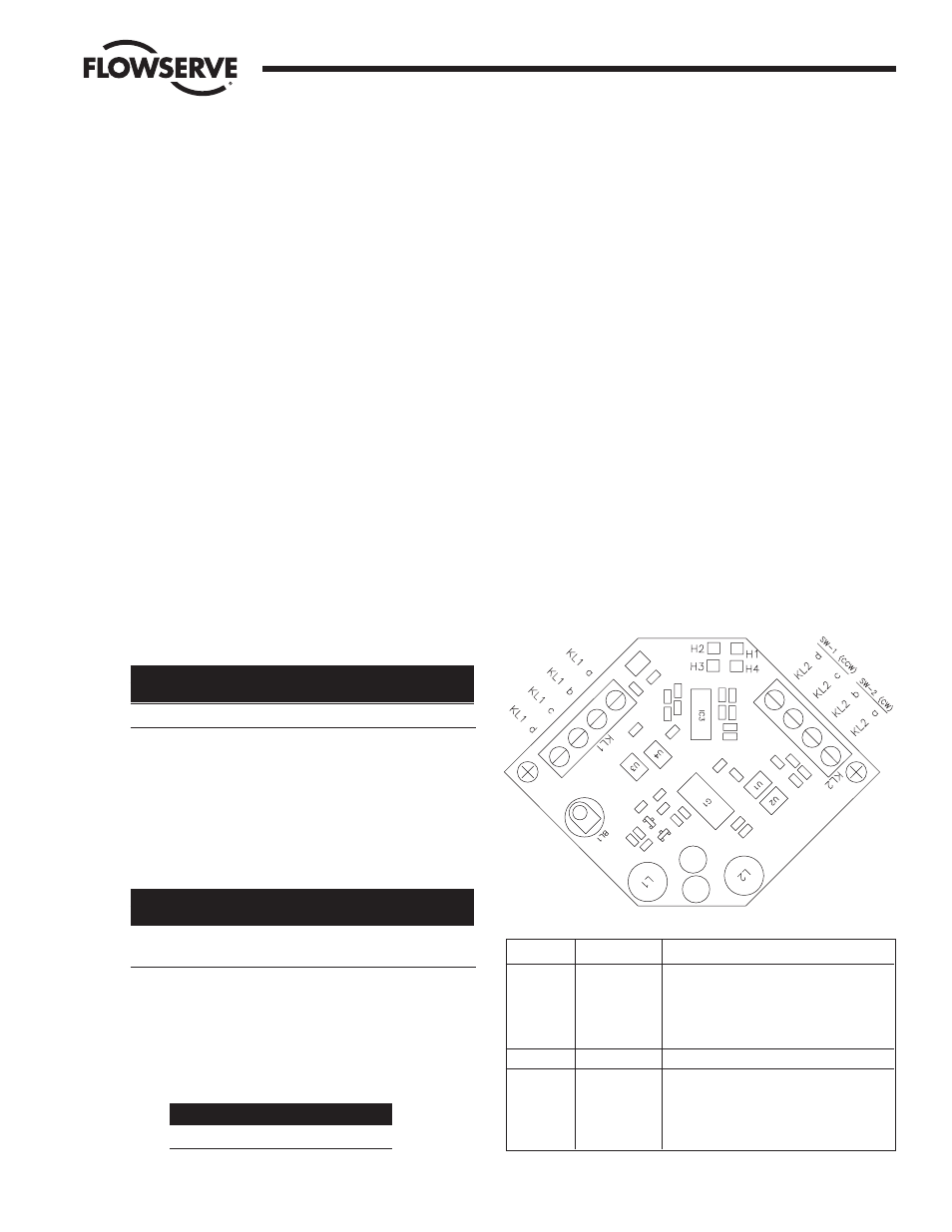
Figure 1
KL1
A
OUTPUT
Solenoid +
B
OUTPUT
Solenoid -
C
AS-I +
D
AS-I -
KL2
A
INPUT
Switch/Sensor 2 +
B
INPUT
Switch/Sensor 2 -
C
INPUT
Switch/Sensor 1 +
D
INPUT
Switch/Sensor 1 -
} CW
} CCW