Flowserve ARG Series Standard Actuator User Manual
Page 8
8
®
User Instructions ARG Series Standard Actuator - ACENIM0123-00 12/12
4 Hydraulic Override
Hydraulic overrides on Worchester Controls heavy duty ac-
tuators provides a low effort, high thrust in compact sized
override, for manually operating the actuator. The hydraulic
overrides are single acting on the SR models and double
acting on the DA actuator for efficient, automatic operation.
These are available on models ARG3 through ARG8.
The hydraulic override consists of a power pack with hand
operated high pressure pump connected by SS tubing, to hy-
draulic cylinder, mounted on spring module on SR models
and on the torque module, on the DA models.
The hydraulic override provides adequate thrust to output the
rated torque on DA models, and required valve torque output
for the operation of SR models.
4.1 Installation
Worchester Controls standard hydraulic overrides are provid-
ed as a complete integral component of the heavy duty actua-
tor. Hydraulic override is shipped with the cylinders mounted
to the actuator and bypass/vent valves installed on the pres-
sure cylinders. The power pack is selected, factory fitted and
connected, as per the application. No additional customer
installation is required. See Worchester Controls Heavy Duty
IOM (FCD WCENIM0121) for instructions on installing Heavy
Duty actuator into service.
4.2 Install hydraulic override onto existing heavy
duty Spring Return actuator (see Fig.: 2)
4.2.1 Disconnect air pressure and electrical power from ac-
tuator.
4.2.2 Remove the end cover plate, retaining the O-ring on
the Spring Module end.
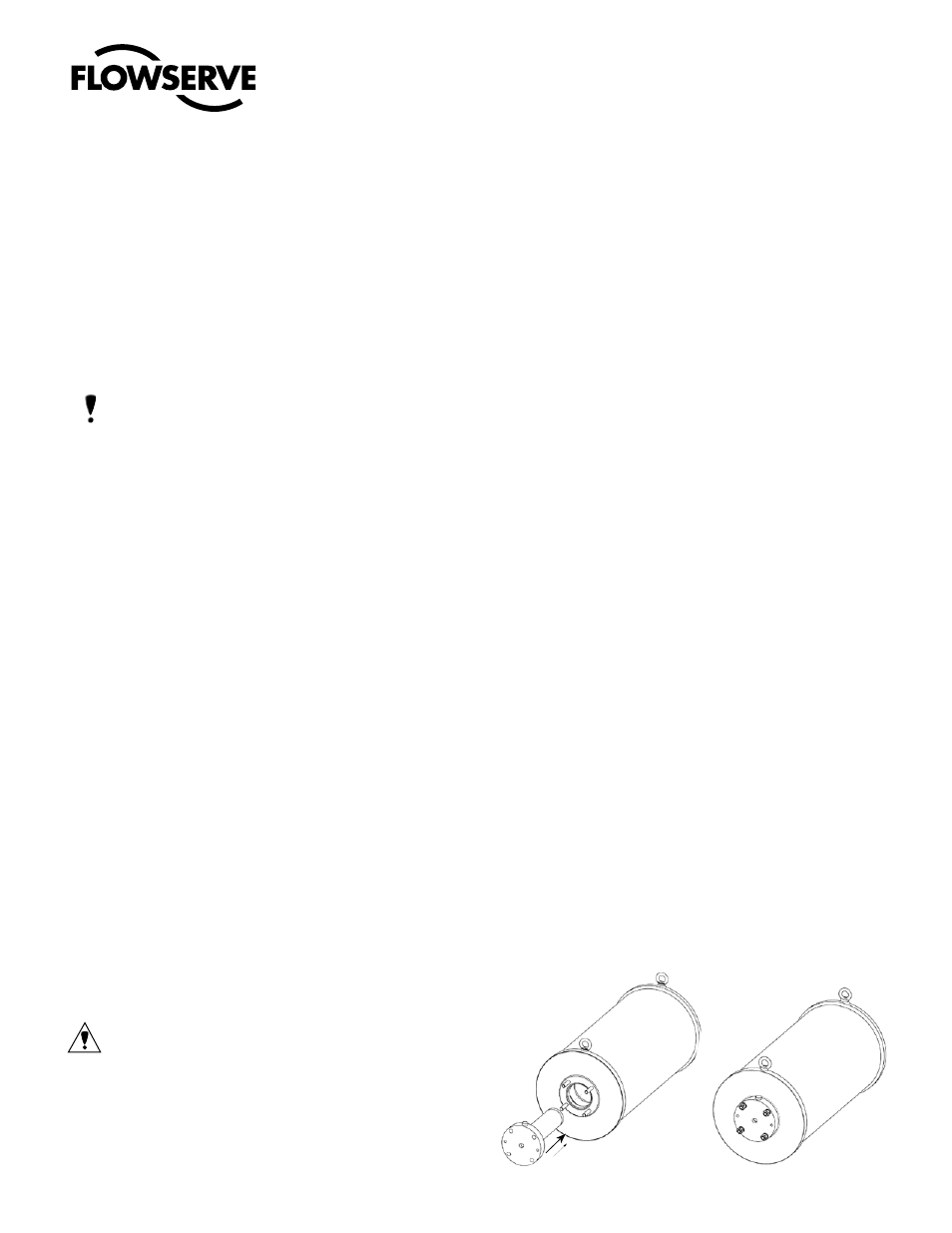
4.2.3 Thread in the studs (1), from the override mounting
kit, into the thrust base and insert the Hydraulic Cylin-
der into the Spring Module to mate the cylinder flange
inner face to the thrust base, keeping the air venting
plug to the top (see Fig.: 1 ).
3.4 Operation
Manual Operation (In the absence of pneumatic pressure
only)
3.4.1 Turn the 3 way valves on the pressure module to vent the
cylinder ports to atmosphere. Ensure all vent valves are
in vent position. Number of these valves varies as per the
actuator type (DA/DD/SR).
3.4.2 Rotate the hand wheel on the manual override until the
position indicator on the manual override agrees with the
valve position.
NOTE: The position indicator on the manual override
indicates actuator/valve position only when the hand
wheel is engaged. (Position indicator shows ‘SHUT’ in
full CW position and ‘OPEN’ in full CCW position)
3.4.3 Engage worm shaft by pulling out the lock pin and ro-
tate the engage-disengage lever 90 degrees till the spring
loaded lock pin drops into the indexed position. Operate
hand wheel to turn the gear override. Follow instructions
on gearbox to engage the worm shaft.
3.4.4 Manually operate the actuator by turning the hand wheel.
See direction markings on the gearbox and turn the hand
wheel accordingly to open/shut the valve.
3.5 Restoring Automatic Operation
3.5.1 Operate hand wheel to desired valve position. This should
be fail safe position, for a spring return actuator.
3.5.2 Pull out the lock pin of the declutch mechanism, out of
locking position, and turn the lever to Disengage the
worm shaft from the wheel. Turn the lever until the lock
pin sits into the indexed position. It may be necessary to
rotate the hand wheel back & forth at the same time the
declutching handle is lifted, to relieve the load on the
declutching pin.
3.5.3 Turn the 3 way valves, on the pressure module ports to
connect cylinder ports to air supply pressure.
3.5.4 Operate actuator normally with pneumatic pressure sup-
ply.
CAUTION! The gearbox override on a spring return ac-
tuator shall not be disengaged while the spring is un-
der compression. Engagement and disengagement of
the worm shaft of the override gearbox should be done
only at the Fail Safe condition of the actuator.
Fig.: 1 Insert Hydraulic Cylinder