Worcester controls – Flowserve 72 Series Electri-SAFE User Manual
Page 5
IMPORTANT: If “ON” time adjustable control is at minimum and/or
“OFF” time adjustable control is at maximum, the actuator will not
rotate. The minimum “ON” pulse must allow the actuator to move
a closed valve out of its seat. Verify proper CLC operation by
opening a fully closed valve.
C. Manual
Operation
In the event of power failure, the Series 72 actuator will cycle to
the fail position, but can be cycled manually. This is accomplished
by applying a wrench to the exposed top shaft of the actuator and
turning it in the desired direction. Note that the actuator will not
remain in the open position until power is restored to the fail-safe,
normally open, solenoid.
a
WARNING: CARE MUST BE TAKEN TO ENSURE THAT THE
ACTUATOR IS NOT OPERATED ELECTRICALLY WHILE MANUAL
OPERATION IS BEING PERFORMED.
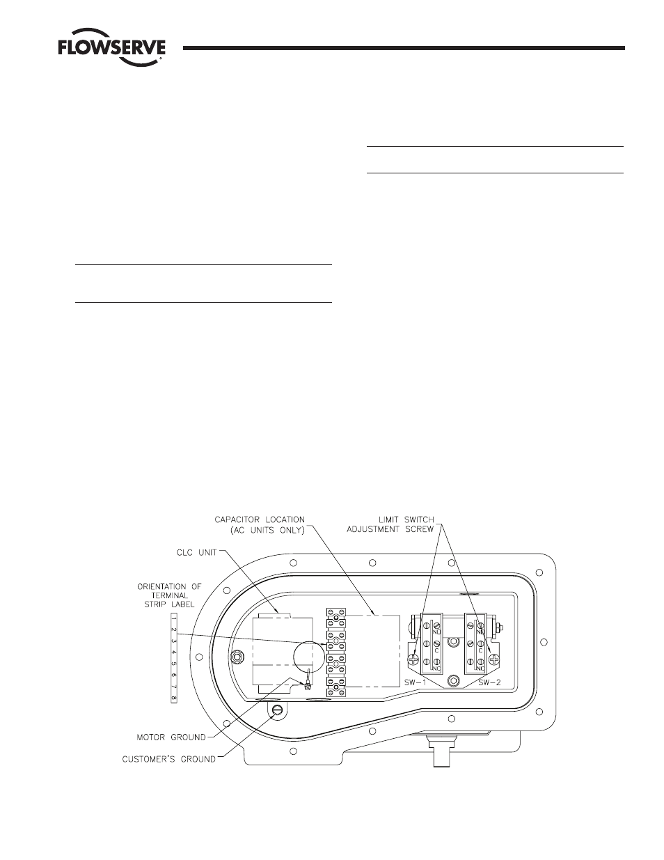
D. Limit Switches
The “standard” mounting configuration of the 72 Actuator to the
valve is in-line, fail-closed. In this configuration, SW-1, as
described in the wiring diagram (shown in electrical installation
section and also located inside the limit switch cover) and shown
in illustration below, will give indication when the actuator is in
the open position, or CCW limit of rotation. SW-2 gives indication
of the closed position, or CW limit of rotation.
Actuator failure position may be changed by either inverting the
actuator or mounting cross-line. In these cases, the limit switch
must be mounted the same as described above, but SW-1 and
SW-2 indication will be reversed from that above. If there is
question as to which switch is going to indicate a given position,
the actuator should be operated, and SW-1 and SW-2 checked to
verify which switch will give the desired indication.
CAUTION: Switches have been factory adjusted but should be
rechecked after installation. Adjustment is as follows:
1. With actuator mounted in "standard" configuration, set
actuator in closed position with the adjustment screw near its
loose limit, adjust closed position switch SW-2 (see
illustration) by tightening the adjusting screw until switch
contacts click. Tighten the adjustment screw an additional
1
/
4
turn.
2. Change actuator to its full open position and adjust open
position switch SW-1.
a) If the actuator does not open fully, back the adjusting
screw out
1
/
2
turn and cycle the actuator.
b) If the actuator opens fully, and the motor continues to
run, tighten the adjusting screw until the switch contacts
click and tighten again by an additional
1
/
4
turn.
c) Cycle the actuator to verify the settings are correct. The
limit switch SW-1 should stop the pump motor when the
actuator is fully open.
3. Make electrical connections for the limit switches to the
terminal strip, if applicable, in accordance with the wiring
diagram inside the limit switch cover.
4. Install the limit switch cover.
WCAIM2049
Series 72 “Electric-SAFE” On/Off Operation Including CLC Option
5
Flow Control Division
Worcester Controls