Worcester controls – Flowserve 10–40 39 ACCESS M Mounted Limit Switch User Manual
Page 4
4
10–40 39 ACCESS M Mounted Limit Switch and Solenoid with AS-Interface
WCAIM2032
c. For fail-open mounting configuration (see Step 2), wire
actuator per appropriate wiring diagram, set actuator in the
full open position with adjustment screw near its loose limit.
Adjust open position switch or Namur proximity sensor SW-
2, by tightening the adjustment screw until the green LED
turns on. Then tighten adjustment screw one additional turn.
With air supplied to actuator, energize the solenoid to change
actuator to its full closed position. The yellow and orange LEDs
should be lit indicating power to the coil and coil continuity,
respectively. Adjust the closed position switch/sensor SW-1 in
the same manner as the open position switch/sensor until the
red LED turns on. Then tighten adjustment screw one
additional turn. When the solenoid is de-energized, the actuator
will return to its full open position. The yellow and red LEDs
will turn off indicating that the solenoid is de-energized and that
the actuator is no longer in the full closed position and then the
green LED will turn on indicating that the actuator is now in the
full-open position.
NOTE: If actuator is mounted in any configuration, other than
“standard” consult Step 2 of Installation Instructions to
ensure proper orientation of probes and switches (sensors).
8. Wiring instructions for limit switches and proximity sensors. Refer
to Step 2 for any actuator mounting configuration other than
“standard”.
Limit Switch/Proximity Sensor Ratings:
Mechanical Switch – 15.1 amps @ 125/250 VAC; .5 amps @
125 VDC.
Namur Proximity Sensor – < 1mA (Target present), > 3mA (Target
absent) 15 mA max., 5-25 VDC, sensing range 2 mm, switching
frequency 1 kHz. Not sensitive to polarity.
Make electrical connections in accordance with the appropriate
wiring diagram on inside of cover or on page 3:
9. Cover
Assembly:
Place the lubricated O-ring down over the threaded section of the
housing onto the machined shoulder. The cover must be threaded
onto housing tightly for proper performance. The assembly is
now complete.
NOTE: For units with a metal cover, a light coat of grease (such as
a #1 grease) shall be applied to the cover threads. A minimum of
1
/
3
the circumference of the threads to be lubricated.
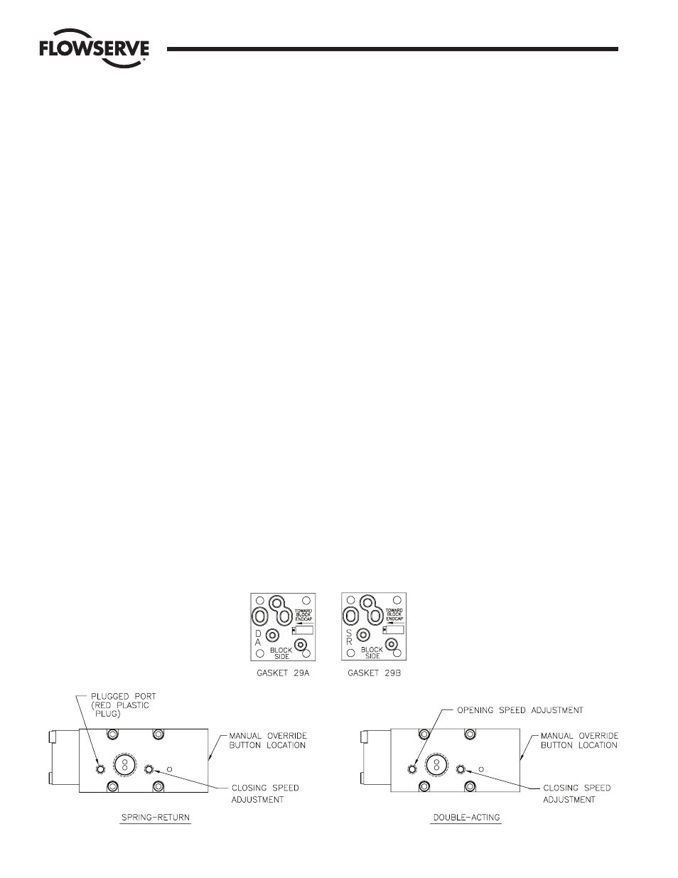
10. Control Block:
If control block is removed, be sure appropriate gasket is properly
inserted between block and switch base (see Figure 1 below and
Access exploded view). Do not apply any grease to gasket, it must
be installed dry.
11. Air Supply Connection:
Connect air supply to
1
/
4
" NPT connection on control block.
12. Operation:
A. Double-Acting with Control Block - Air is supplied to the
1
/
4
"
NPT port on the block. When the solenoid is energized, the
spring-loaded plunger is withdrawn; allowing the supply air to
shift the spring-loaded spool within the block, which opens
the supply path to the center chamber of the actuator. Air
from the end chambers of the actuator is allowed to pass
through the block and exhaust to atmosphere.
When the solenoid is de-energized, the spring-loaded plunger
blocks the flow of air to the spool seal within the block and the
spool spring shifts the spool within the block to a position
which opens the supply path to the end chambers of the
actuator. Air from the center chamber of the actuator is
allowed to pass through the block and exhaust to atmosphere.
The actuator is electrically fail-safe. That is, it will return to its
de-energized position upon electrical failure.
Flow Control Division
Worcester Controls
Figure 1
Figure 2