Flowserve Lockout Module User Manual
Lockout module, Installation instructions, Operation
Flowserve Corporation
765 South 100 East
Phone: 801 373 3028
Flow Control Division
Provo, Utah 84606
Facsimile: 801 489 2228
Automation Business Unit
www.flowserve.com
Email: [email protected]
© 2001, Flowserve Corporation, Provo, UT
Automax Valve Automation Systems
Installation, Operation and Maintenance Instructions
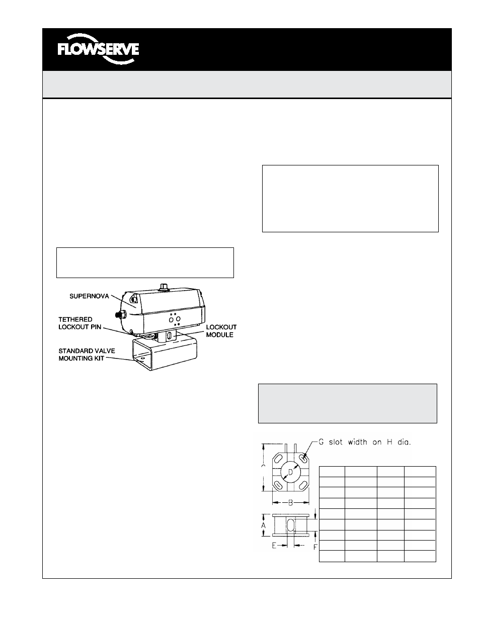
Lockout Module
Reference Dimensions
Dim.
LOM1 LOM2 LOM3
A
1.63
2.13
2.75
B
2.34
3.93
6.01
C
3.00
4.96
7.31
D
1.62
3.00
4.76
E *
0.53
0.78
1.06
F *
1.16
1.53
1.81
G
0.37
0.57
0.71
H
2.21
3.89
6.01
* (4) places centered on housing
Installation Instructions
The Automax Lockout Modules allow simple mechanical
lockout to new and existing Automax SuperNova valve/
actuator assemblies. Three models of the Lockout Module
mount directly to the SNA063 through the SNA200, as well
as the N63 through the N250, and the A75 through the
A250. The Lockout Module provides a compact mechanical
lockout assembly which when properly implemented will
satisfy OSHA Standard 1910.47, “The Control of Hazard-
ous Energy.” The Lockout Module mounts directly between
a standard valve mounting kit and a SuperNova actuator,
requiring only a special coupler for the specific valve/actua-
tor combination. This allows for easy field retrofit of
a mechanical lockout device to existing valve/actuator as-
semblies.
Note: The Automax Lockout Module is not
suitable for valves requiring a constant positive
shut-off torque to ensure sealing.
To install:
1. Note valve position, open or close. Move valve to
desired lockout position. The actuator should be in
a corresponding position.
2. Apply a thread-locker, Locktite 242 or equivalent
to the mounting studs, and mount studs to actuator.
3. Mount standard valve mounting kit to valve.
4. Install Lockout coupler to valve stem, properly
orienting coupler for desired actuator position.
5. Position Lockout Module as desired on top of
mounting kit. Place actuator over Lockout Module,
aligning coupler and actuator pinion.
6. Tightens nuts until snug. Stroke actuator several
times to properly align coupler.
7. With actuator and valve in desired locked out
position, loosen nuts and rotate Lockout
Module
about valve stem axis, until the
hole in the Lockout
coupler aligns with the slots in the Lockout Module
housing.
8. Insert the Lockout pin through the Lockout
coupler, to hold Lockout Module in position while
tightening bolts. Tighten mounting nuts to actuator.
Note: When locking out a high-performance
butterfly valve, or other valves with “quick
opening” characteristics, bias the lockout
module housing against the lockout pin. To
lockout a HPBV in the closed position, rotate
housing CW against pin to keep valve from
opening CCW.
9. Remove Lockout pin from coupler and insert into
storage brackets on the side of Lockout Module
housing.
Operation
The Lockout pin may be stored and locked in the storage
brackets extruded into the Lockout housing.
To lock out a valve, position valve in desired setting. The
hole in the Lockout coupler should align with the slots in
the Lockout housing. Insert the Lockout pin through the
hole in the Lockout coupler, and apply a lock to the end of
the pin extending from the other side of the Lockout hous-
ing.
WARNING: Do not stick foreign objects, such as fingers,
screwdrivers etc. into Lockout hole. Serious injury may
result. Use only Lockout pin supplied with Lockout Module
to lock out actuato
r.
LMR0022-1 (AUTO-19) 01/11
PAGE 1 OF 2