Worcester controls – Flowserve 93 Series PULSAIR III User Manual
Page 4
4
Series 93 PULSAIR III Digital Electronic Positioner Installation, Operation and Maintenance
19860-C
Flow Control Division
Worcester Controls
10. Install the cam assembly with the lobes oriented towards the
terminal strip end of the positioner, over the positioner shaft.
Move the switch contact arms (M2 mechanical switches
only) aside so that the cam assembly can sit all the way
down on the shaft.
NOTE: Cam assembly does not have to be installed, if switches are
not going to be used and only the 4–20 mA output is to be utilized.
CAUTION: For m2 mechanical switches, Do not force the CAM
assembly down without moving the contact arms, as damage to
the limit switch may result.
11. Rotate the cam assembly to line up the cam assembly
attachment screws and tighten the screws finger tight. You
should still be able
to move the cams for alignment before final tightening of the
attachment screws.
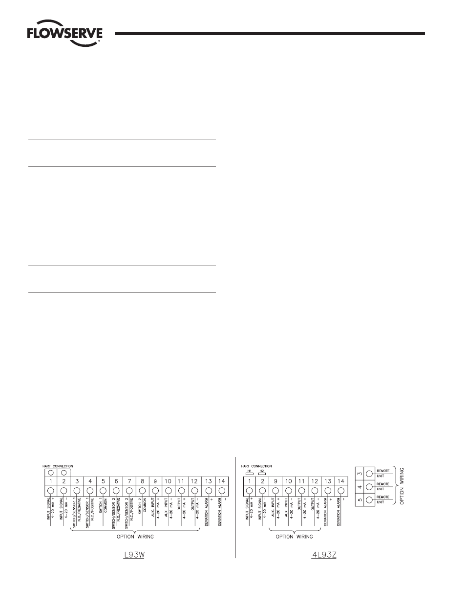
6. Electrical
Connections
See wiring diagram (9) on inside of cover (refer to Figure 1 for
wiring label location) or Figure 3 below.
a
WARNING: In a hazardous environment where there is a risk of
explosion, electrical connections must comply with the relevant
regulations.
Remove the positioner cover (if not already done) for connecting
signal source and for optional board wiring. NOTE: For 4L93Z
units there are separate covers for programming and electrical
connections.
Connect a 4–20 mA signal source to terminal locations 1
(positive lead) and 2 (negative lead).
Adjust the signal source to between 8 and 20 mA.
For 4–20 mA output module option
(for L93W & 4L93Z Positioners)
Connect a 10-28 volt DC source to terminal locations 11
(positive) and 12 (negative return from load).
For M2 Limit or R2 proximity switch option
(for L93W Positioner only)
M2- Connect 125 VAC- 3 amp maximum, or 30 VDC - 2 amp
maximum wiring to terminal locations as follows:
R2 - Connect 125 VAC or 30 VDC - 250 mA maximum wring to
terminal locations as follows:
Terminal Locations:
3
Clockwise switch, normally open - Switch #1
4
Clockwise switch, normally closed - Switch #1
5
Clockwise switch, common - Switch #1
6
Counter-Clockwise switch, normally open - Switch #2
7
Counter-Clockwise switch, normally closed - Switch #2
8
Counter-Clockwise switch, common - Switch #2
For P2 Namur Sensor Option
(for L93W Positioner only)
Connect appropriate Namur amplifier (rated for 5–25 VDC
output) wiring to terminal locations as follows:
Terminal Locations:
3
Clockwise Sensor, negative - Sensor #1
4
Clockwise Sensor, positive - Sensor #1
6
Counter-Clockwise Sensor, negative - Sensor #2
7
Counter-Clockwise Sensor, positive - Sensor #2
For open collector alarm output
Connect 8–28 VDC wiring to terminal location 13 (positive) and
14 (negative).
Menus and Pushbuttons
The positioner is controlled using the five pushbuttons and the
display, which are accessible when the positioner cover is removed.
For normal functioning, the display shows the current position value.
Press the ESC button for two seconds to display the main menu.
Figure 3