Wiring, Worcester controls – Flowserve 90 Series Heater Kit User Manual
Page 2
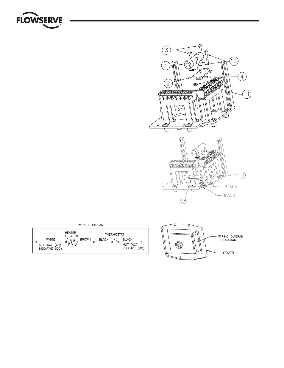
If two terminal strips are present:
Note: Some kit parts will not be used.
4. Remove the two screws that retain ther terminal block (item 11)
to its bracket.
5. Mount the heater assembly to the top of the terminal block using
two #4 x 1" self-tapping screws (item 12) provided.
For one and two terminal strips:
6. Locate the thermostat (item 13) in a convenient location — away
from rotating parts. One suggested location is shown in the sketch
at right. Use a wire tie (item 14) to hold the thermostat in place.
WIRING
The heater must be connected to a constant (non-switching) power
supply to maintain internal temperature. If intermittent use is desired,
power to the heater can be switched.
Make connections using the closed end splices provided. Note that no
connections will be made to the terminal strips.
Refer to wiring diagram below.
1. Connect the white wire from the heater element to the neutral
(if AC) or negative (if DC) side of the power supply.
2. Connect the brown wire from the heater element to one of the
black leads from the thermostat.
3. Connect the other black wire from the thermostat to the hot
(if AC) or positive (if DC) side of the power supply.
4. Attach wiring diagram to inside end of M.A.S. cover as shown
below.
Flow Control Division
Worcester Controls
Flowserve Corporation has established industry leadership in the design and manufacture of its products. When properly selected, this Flowserve product is designed to perform its intended function
safely during its useful life. However, the purchaser or user of Flowserve products should be aware that Flowserve products might be used in numerous applications under a wide variety of industrial
service conditions. Although Flowserve can (and often does) provide general guidelines, it cannot provide specific data and warnings for all possible applications. The purchaser/user must therefore
assume the ultimate responsibility for the proper sizing and selection, installation, operation, and maintenance of Flowserve products. The purchaser/user should read and understand the Installation
Operation Maintenance (IOM) instructions included with the product, and train its employees and contractors in the safe use of Flowserve products in connection with the specific application.
While the information and specifications contained in this literature are believed to be accurate, they are supplied for informative purposes only and should not be considered certified or as a guarantee of
satisfactory results by reliance thereon. Nothing contained herein is to be construed as a warranty or guarantee, express or implied, regarding any matter with respect to this product. Because Flowserve
is continually improving and upgrading its product design, the specifications, dimensions and information contained herein are subject to change without notice. Should any question arise concerning
these provisions, the purchaser/user should contact Flowserve Corporation at any one of its worldwide operations or offices.
For more information about Flowserve Corporation, contact www.flowserve.com or call USA 1-800-225-6989.
FLOWSERVE CORPORATION
FLOW CONTROL DIVISION
1978 Foreman Drive
Cookeville, Tennessee 38501 USA
Phone: 931 432 4021
Facsimile: 931 432 3105
www.flowserve.com
© 2003 Flowserve Corporation, Irving, Texas, USA. Flowserve and Worcester Controls are registered trademarks of Flowserve Corporation.
09258-D 9/03 Printed in USA