Flowserve Aviator II Valve Controller User Manual
Installation operation, Aviator ii valve controller, Maintenance
Installation
Operation
Automax Valve Automation Systems
Aviator II Valve Controller
FCD AXENIOM0100-02
Maintenance
Mechanical Installation:
Installation is best performed with the NAMUR mounting kits. These kits allow direct
mounting of the Aviator™II shaft to the actuator pinion without a coupler. The NAMUR mounting kits will work with any
actuator conforming to the NAMUR standard for accessory mounting hole locations and pinion dimensions. Simply attach
bracket to actuator and Aviator™II to bracket with the included fasteners. The Aviator™II shaft features an integral
alignment pin which engages the tapped pinion hole. Automax also offers a full line of non-NAMUR kits.
Electrical Connections:
The Aviator™II features three (3) 3/4" NPT conduit entries. The switches and pilot solenoid
are pre-wired to the screw terminal block to simplify customer wiring connections. A wiring diagram is included under the lid.
Simply make desired connections to the screw terminal blocks. Secure a grounding wire under the green grounding screw.
Make sure the solenoid control voltage is the same as the solenoid electrical rating. For hazardous locations, U.L. and
National Electric codes require an approved sealing fitting within 18 inches of the switch enclosure. Sealing fittings are not
required for Division 2 non-incendive applications. Open conduit entries must be closed after installation using a close-up
plug approved for hazardous locations. Conduit and plugs must engage a full five (5) threads.
For field wiring: ensure that any excess wire lengths or loops are routed away from any moving parts and are short
enough, or secured to ensure a ¼” clearance between the wire and the inside surface of the switchbox cover.
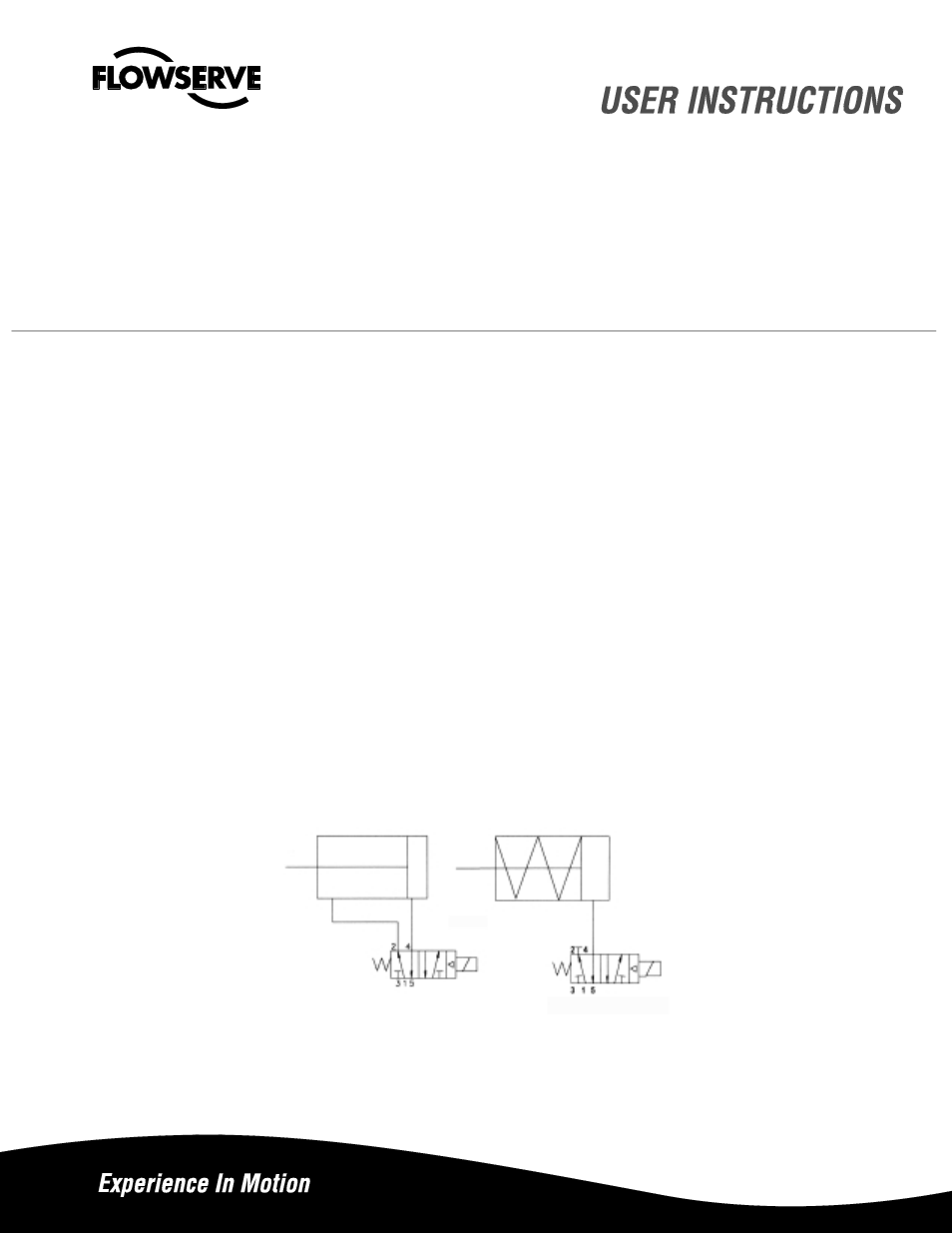
Spool and Tubing Configuration
: For spring return actuators, a 4-way spool valve is provided with port #2
plugged. For double acting actuators, the same spool valve is provided with no plugs. Make sure the correct spool is
selected before installing tubing. (Note: the APS2 module can be supplied on spring return actuators to purge the spring
chamber with supply air.) 2. Make sure all air pressure is removed before installing tubing. 3. Attach tubing according to
Figures 1 or 2 below, depending upon application. Attach supply tubing to Port 1 and use 3 and 5 exhaust. 4. To prolong
actuator life use only clean, dry plant air. Lubricated air is not required, although it is recommended particularly for high
cycle applications.
NOTE:
A minimum of 35 psi is required to operate the spool valve.
Figure 1 Figure 2
Double Acting Actuator
Spring Return Actuator
Caution:
To prevent ignition of hazardous atmospheres, keep cover bolts tight while circuits are live. Disconnect supply
circuit before opening removing the lid. Do not place the lid with the flat surfaces down. This will ensure that the flange is not
damaged and integrity of the flame path will be maintained.