Flowserve CE DC Brake User Manual
Ce dc, Brake assembly kit
Flowserve Corporation
11444 Deerfield Road
Phone: 513 489 7800
Flow Control Division
Cincinnati, Ohio 45242
Facsimile: 513 489 5243
Automax Valve Automation Systems
www.flowserve.com
Email: [email protected]
©
1998, Flowserve Corporation, Cincinnati, OH
CE DC
Brake Assembly Kit
LME0008-0
Page 1 of 4
Assembly Procedure
1. Disconnect all power to the actuator.
2. Remove the actuator cover.
3. The accessory mounting bracket will have to be
replaced. To replace, remove the bolts that fasten the
bracket to the motor and base plate. Remove
potentiometer gear (if installed) and any switch wires.
Lift the bracket away from the base. Remove any
existing items such as a terminal strip, cut-off switch,
pop-in shaft bearing, etc.
4. Bolt the new accessory bracket P/N 109469 to the
motor mounting plate.
5. Remove any existing fan (pressed in place) from the
top of the motor rotor shaft.
6. Attach the fan hub P/N 108534 to the motor rotor
shaft using the #10-32 set screw.
7. Place the wave spring P/N 108198 onto the
fan hub and the spacer shim P/N 108199
onto the wave spring.
8. Next, place the black plastic fan P/N 107940 onto the
hub. Squeeze the fan against the spring. Place
the brass washer P/N 108361 and clip the snap ring
P/N 106174 onto the groove in the top of the hub.
9. Now place the two bronze spacers P/N 108296 onto
the Bracket Spacer P/N 106193 so that the flange is
down and the small diameter fits into the mounting
feet holes of the hinge. Place two washers P/N
100986 under the bronze bearing on Bracket
Spacer(13). This will serve to level the hinge.
10. Place the hinge assembly over the bronze bearings
P/N 108296 and bolt to Bracket Spacer (13), and
accessory bracket with (2) washers P/N 100986.
11. Insert the spring P/N 103714 into the solenoid
(P/N 109479 or 109555) and attach the solenoid, and
the Spacer P/N 109468 to the accessory bracket with
the two socket head cap screws P/N 102846.
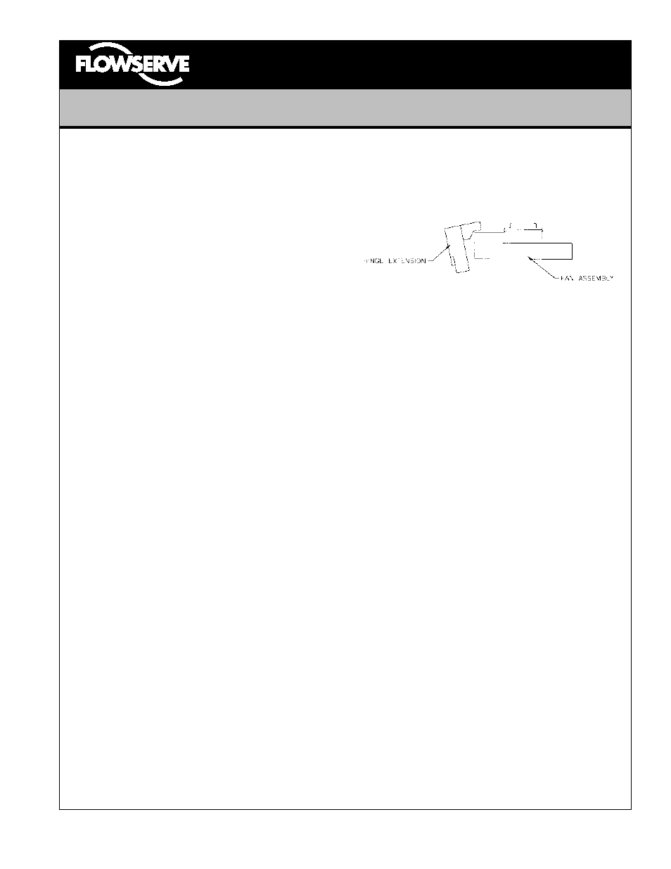
12. The solenoid and hinge extension should be adjusted
such that when it is energized, the extension just
clears the spinning fan.
13. Re-attach all items removed in step 3 including:
terminal strip, cutoff switch, pop-in shaft bearing, etc.
14. Attach the leads of the solenoid as shown in the
wiring schematic. The solenoid is not polarity sensitive.
Use wire connectors P/N 105453 to connect the
solenoid and the motor wires according to the wiring
schematic.
Operation
Following are a few key pointers to ensure proper operation:
1. The hinge needs to float freely on the bronze spacers
without binding up. Test the freeness of the hinge
several times by pulling it back against the spring
using your fingers.
2. Be careful to not overtighten the screws holding the
hinge on. They may bind up the assembly.
3. Adjust the solenoid as close to the hinge as possible
so the assembly just clears the gears of the
potentiometer. A shorter pull on the solenoid allows
for a stronger release. Be sure to allow the hinge to
float against the plunger and not bind up.
9/98