Flowserve Centura CE Extra-Switch User Manual
Flowserve Hardware
©
2000, Flowserve Corporation, Provo, Utah
3-Position Control/Dribble Control
SR Limit Switch Method
Flowserve Corporation
765 South 100 East
Phone: 801 373 3028
Flow Control Division
Provo, Utah 84606
Facsimile: 801 489 2228
www.flowserve.com
Email: [email protected]
Automax Valve Automation Systems
Installation, Operation and Maintenance Instructions
Caution:
To prevent ignition of hazardous atmospheres, keep unit tight while circuits are alive. Disconnect supply circuit
before opening.
SWITCHES
Adding extra switches to the CENTURA CE series actuator requires a Single Switch Kit (P/N 108474) or a Dual Switch Kit
(P/N 108475).
1) Disconnect all power to the actuator.
2) Remove the actuator cover.
3) The accessory mounting bracket must first be removed. Remove the bolts that fasten the bracket to the motor and the
base plate. Remove potentiometer gear (if installed) and any switch wires. Lift the bracket away from the base.
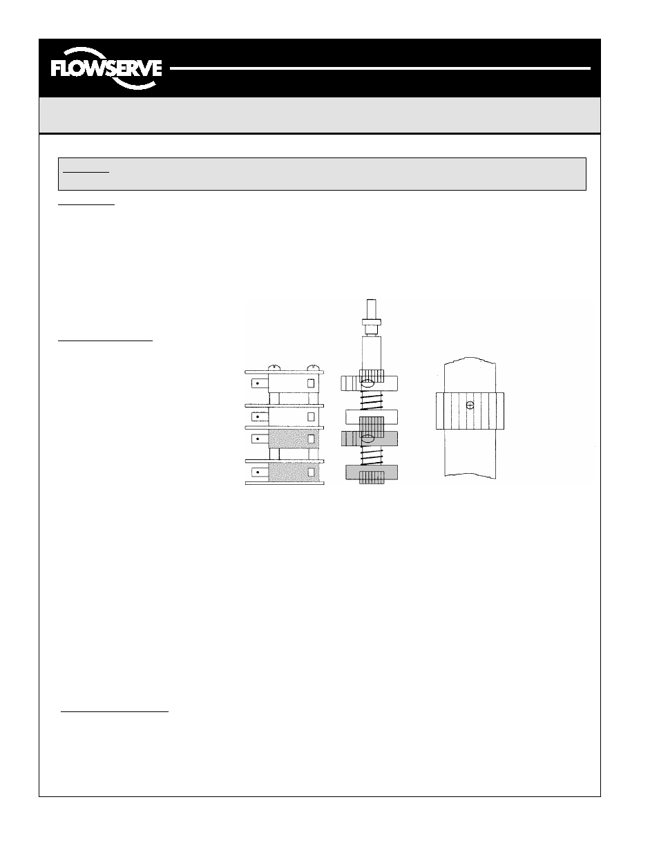
4) After the accessory mounting is removed, remove existing switches. Note the orientation of the switch stack. Here is an
example of proper switch stacking:
FROM TOP DOWN
1. Insulator
2. Switch
3. Nylon Spacer
4. Insulator
5. Switch
6. Insulator
7. Switch
8. Nylon Spacer
9. Insulator
10. Switch
11. Insulator
Switch
Stack
Orientation
Cam
Stack
Orientation
Auxiliary 2
Auxiliary 1
CW Switch
CCW Switch
Note: Roll pin
hole is not
centered to the
length of the
spline. Install
as shown.
5) After stacking the proper amount of desired switches, extra cams will need to be installed. The first extra cam is simply
slid over the end of the cam shaft. Make sure the female side of the cam faces toward the actuator base, and slides
securely over the male splines. Next slide the supplied spring over the camshaft. Now, if two extra switches are being
installed, slide the second extra cam over the camshaft with the female side facing upward. While compressing the
spring, slide the male spline over the camshaft as pictured above (with longer end of the spline facing downward
towards the base) and insert the supplied roll pin to hold in place.
6) Re-install the accessory mounting bracket and re-connect the wires as per the schematic located inside the cover.
7) Attach the supplied terminal strip to the leg of the accessory bracket. The mounting holes are located near the “right”
conduit entry (as shown in the drawing).
8) Wire the extra switches per the supplied schematic.
9) Attach the supplied schematic sticker to the inside of the actuator cover for future reference.
10) When replacing the cover, the machined joints must be clean and clear of any obstructions. The integrity of the
explosion-proof rating depends on the care of these joints.
* Refer to Installation Instructions for proper cam adjustment. (The micro adjust set screws in the cams are set as follows:
Aux. Switch 1 is for CCW adjustment Aux. Switch 2 is for CW adjustment.)
HEATER & THERMOSTAT
* Disconnect power to the actuator before installing heater and thermostat.*
1 ) The heater & thermostat come in a kit, with the wires already spliced together.
2) The heater is simply screwed into the left, front mounting hole on the gearmotor (as shown in the drawing).
3) The thermostat is then wire tied to the existing wire bundle near the leg of the accessory bracket.
4) The white wire is twisted to the motor common wire and both are inserted into the #1 terminal strip location.
5) The black lead of the thermostat is then inserted into the #6 terminal strip location.
LML0008-1 (AUTO-44) 12/00
Page 1 of 2
Centura CE Extra-Switch & Heater & Thermostat Installation