Esp3 transmitter (optional), Resistive inputs (optional), Heater & thermostat (optional) – Flowserve ESP3 Electronic Servo Positioner User Manual
Page 2: Performance data (centura/esp3)
© 2001, Flowserve Corporation, Provo, Utah
3-Position Control/Dribble Control
SR Limit Switch Method
Flowserve Corporation
765 South 100 East
Phone: 801 373 3028
Flow Control Division
Provo, Utah 84606
Facsimile: 801 489 2228
Automation Business Unit
www.flowserve.com
Email: [email protected]
Automax Valve Automation Systems
Installation, Operation and Maintenance Instructions
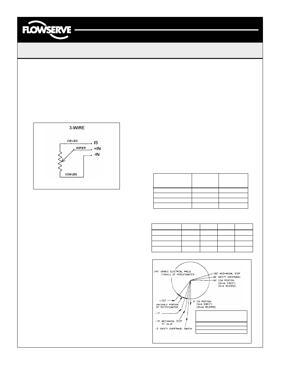
Resistive Inputs (optional)
3 wire: Clockwise rotation of input potentiometer increases signal
(increase resistance). Connect potentiometer’s clockwise lead to
terminal marked IS. Connect counter-clockwise lead to terminal
marked -IN. Connect potentiometer’s wiper lead to terminal
marked +IN. Remove JP1 input select jumper.
Note: If clockwise rotation of potentiometer does not rotate actuator
in an increasing signal direction, reverse potentiometer leg leads.
Important Notes About Reverse Acting
ESP3 with Transmitter
Note: Reverse acting transmitter means a 4mA output for full
CCW, and a 20mA output for full CW position.
1.
The BLUE and GREEN feedback potentiometer wires have
been reversed on TB1 (see chart below).
2.
The feedback potentiometer voltages as measured from
test points ‘A’ to ‘G’ on the ESP3 card are as follows:
CCW ~ 0 .75 Vdc
CW ~ 4.70 Vdc
3.
JP2 and JP3 (Direct / Reverse acting jumpers) are to be on
Heater & Thermostat (optional)
1.
115 Vac heater and thermostat are connected to TB1
terminals L1 and N on the ESP3 servo board (see Wiring
Diagram on page 3).
ESP3 Transmitter (optional)
Note: If the ESP3 Transmitter is used, the servo calibration (p.1) must
be completed with the 4-20mA transmitter installed Servo calibration
should be performed before transmitter calibration.
1.
Connect 4-20mAdc output leads to transmitter
terminals marked ‘+’ and ‘-’.
2.
Place transmitter JP1 jumpers to positions 1-3 and 2-4
for 90 degree operation,or positions 1-2 and 3-4 for
actuators calibrated for 180 degree operation.
3.
Drive actuator to the full CCW position and adjust ‘S’
span adjustment for 20mA output.
4.
Drive actuator to the CW position and adjust ‘Z’ zero
adjustment for 4mA output.
5.
Repeat steps 3 and 4 until the desired output is achieved
in both positions.
6.
Standard ESP3 transmitters are direct acting. A low
output signal indicates CW position and high output
signal indicates CCW position. For reverse acting
see below.
7.
The transmitter is self powered and optically isolated
from the AC motor drive circuits.
LMP0003-1
(AUTO-42)
04/01
Page 2 of 4
‘D’ Direct (left two posts).
4.
The RED and BLACK motor drive leads on TB2 have been
reversed (see chart below).
5.
The drive LED’s will now indicate the opposite of the
actual drive travel.
Reverse
Standard
Wire
Transmitter
Transmitter
Position
Position
BLUE (Feedback Pot.)
P1
P3
GREEN (Feedback Pot.)
P3
P1
RED (Motor Drive)
CW
CCW
BLACK (Motor Drive)
CCW
CW
CE2ATA
CE4ATA
CE7ATA
CE1ATA
LINEARITY
+/-1%
+/-1%
+/-1%
+/-1%
RESOLUTION
2.0
°
1.8
°
1.8
°
1.5
°
DEADBAND
+/-0.8%
+/-0.7%
+/-0.5%
+/-0.3%
HYSTERESIS
+/-1.0%
+/-0.8%
+/-0.5%
+/-0.5%
Performance Data (Centura/ESP3)
ACTUATOR ANGLE
FEEDBACK VOLTAGE
(DEGREES)
OF POTENTIOMETER
(TPA TO TPG)
-5
°
PAST CW
~0.53 VOLTS
0
°
CW POS.
~0.75 VOLTS
90
°
CCW POS.
~4.70 VOLTS
ESP3 FEEDBACK POTENTIOMETER
RESISTIVE INPUT CONFIGURATIONS