Flowserve SR Limit Switch Method 3-Position Control User Manual
Flowserve Hardware
© 2002, Flowserve Corporation, Printed in USA
3-Position Control/Dribble Control
SR Limit Switch Method
Automax Valve Automation Systems
Installation, Operation and Maintenance Instructions
Flowserve Corporation
765 South 100 East
1978 Foreman Dr.
Flow Control Division
Provo, Utah 84606
Cookeville, TN 38501
www.flowserve.com
Phone: 801 373 3028
Phone: 931 432 4021
LML0004-0 (AUTO-34) 3/02
Page 1 of 2
Introduction
The Automax UltraSwitch XLA series limit switch is designed to
operate an automated valve package through three distinct
positions with the mid position fully adjustable. The XLA series
can be easily mounted to an Automax SuperNova spring return
actuator with line mounted 3-way and 2-way solenoid valves
mounted in series for a complete 3-position control package. In
the event of electrical or pneumatic failure, the springs return the
actuator to the fail position. The XLA UltraSwitch utilizes
adjustable cams for precise mid-position calibration. Stopping in
the center for a 3-way valve or stopping near the end of travel for
tank topping dribble control is easily accomplished by adjusting
the pinpoint accurate cams.
Operation
(see schematic 807451 on back)
The Spring Return limit switch method 3-position control package
utilizes the Automax UltraSwitch XLA series limit switch complete
with a 3-way and a 2-way solenoid valve. The XLA series limit
switch contains (2) 15 amp SPDT mechanical switches with an
integral cam assembly for mid-position control. Power to terminal
block connection #7 will drive the actuator counterclockwise
(CCW). Power to terminal block connection #6 and #7 will drive
the actuator to the mid position from the clockwise (CW) position.
Power to terminal block connection #6 will drive the actuator to the
mid position from the CCW position. With both solenoids
de-energized, the springs will fail the actuator to the full CW
position. At the preset mid-position, the top and bottom switches
will trip simultaneously, energizing the 2-way solenoid valve and
locking the actuator in place.
Calibration
1.
Loosen the (4) captive cover screws of the UltraSwitch and
remove the lid, turning slightly while lifting.
2.
Loosen the setscrews in the top cam to allow free rotation of
the integral cams.
3.
Jog the actuator to the desired mid-position by depressing
the solenoid override or applying power to the solenoid.
Energizing the 2-way solenoid valve will block air in the
actuator at the desired mid position.
4.
Adjust the top cam to trip the switch. The switch should
remain tripped from the full CW to the mid position.
5.
Tighten the setscrews in the top cam.
6.
Loosen the lock-down screw on the top cam.
7.
Adjust the bottom cam to trip the switch. The switch should
remain tripped from the mid to the full CCW position.
8.
Tighten the lock-down screw to secure the position of the
bottom cam.
9.
For accurate setting of the mid position, see calibration notes
below.
10. Clean the base and lid flanges of the UltraSwitch and replace the
lid on the base. Make sure the wires are not caught between
the flanges, and tighten the captive cover screws.
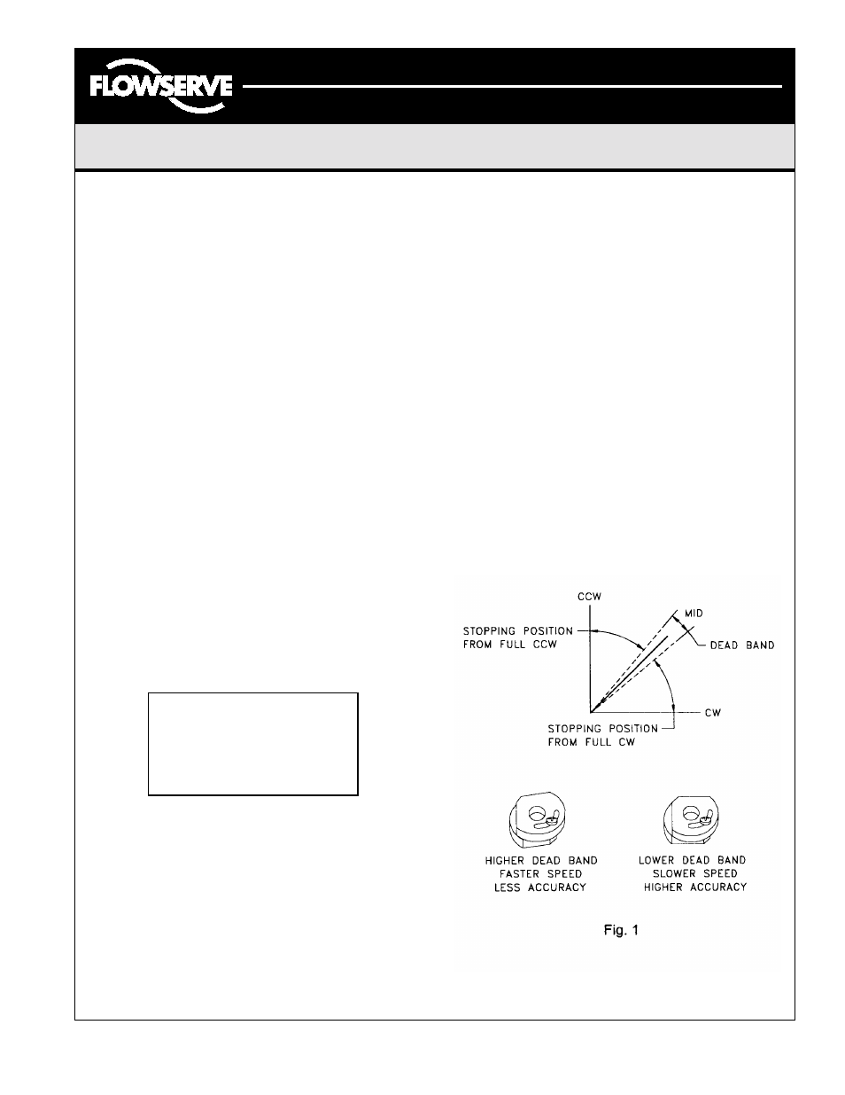
Calibration Notes
The accuracy of the mid position and speed of operation are
interdependent. If a more precise location of the mid position is
required, then the speed of operation must be reduced through the
adjustment of the speed controls. If a faster speed of operation is
required, the mid position must be calibrated with a higher dead
band, thus reducing the accuracy of the mid position. (Dead band is
the overlap between the switches.) (see Fig. 1).
3-Position Control/Dribble Control SR Limit Switch Method
CAUTION:
To prevent ignition of hazardous
atmospheres, keep unit tight while
circuits are alive. Disconnect supply
circuit before opening.