2 film/screen resolution limits – Fluke Biomedical 07-553 User Manual
Page 6
Nuclear Associates 07-553
Operators Manual
1-2
Table 1-1 tabulates the spatial frequency associated with each of the index marks. A larger line
separates the pattern into a group of line pairs with longer lines corresponding to groups of 0.5, 1, 2, 5,
and 10 line pairs per millimeter.
Table 1-1 Line Pairs/mm Value for each Resolution Group
LP/mm
LP/mm
1 0.25
12 2.9
2 0.5
13 3.5
3 0.6
14 4.2
4 0.7
15 5.0
5 0.85
16 6
6 1.0
17 7
7 1.2
18 8.5
8 1.4
19 10
9 1.7
20 8.5
10 2.0
21 7
11 2.4
22 6
1.2 Film/Screen Resolution Limits
1. Place the test plate on top of a test film. Do not use a grid.
2. Use a 40” focus-film distance and 50-60 kVp. Center the tube over the test plate. Adjust the mAs
for a gross optical density of about 1.5 on a portion of the film not covered by the test plate. (These
factors give minimum geometric effects and sufficient contrast to assure a reliable test.)
3. Determine the limiting resolution by inspecting the finished radiograph with a 5-10 power
magnifying glass.
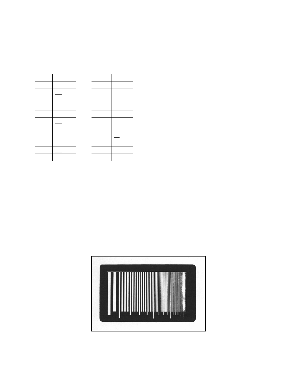
Figure 1-2 is a study of a par-speed film and par-speed screen system. The technical factors were 60
kVp, 3 phase, 4 mAs, normal processing. The limiting resolution, as measured on the original radiograph
was 7 line pairs per millimeter.
Figure 1-2