Operation, 1 operation – Fluke Biomedical 07-644 User Manual
Page 7
Operation
Operation
2
2-1
Section 2
Operation
2.1 Operation
Center the x-ray tube with respect to the image receptor both longitudinally and transversely and adjust
the height of the tube to the proper source to image (SID) distance for the grid employed on the system.
Lock the tube in place. Position an 8" x 10" (20 x 25 cm) or larger cassette in the tray so that the long
dimension of the cassette is perpendicular to the long dimension of the table.
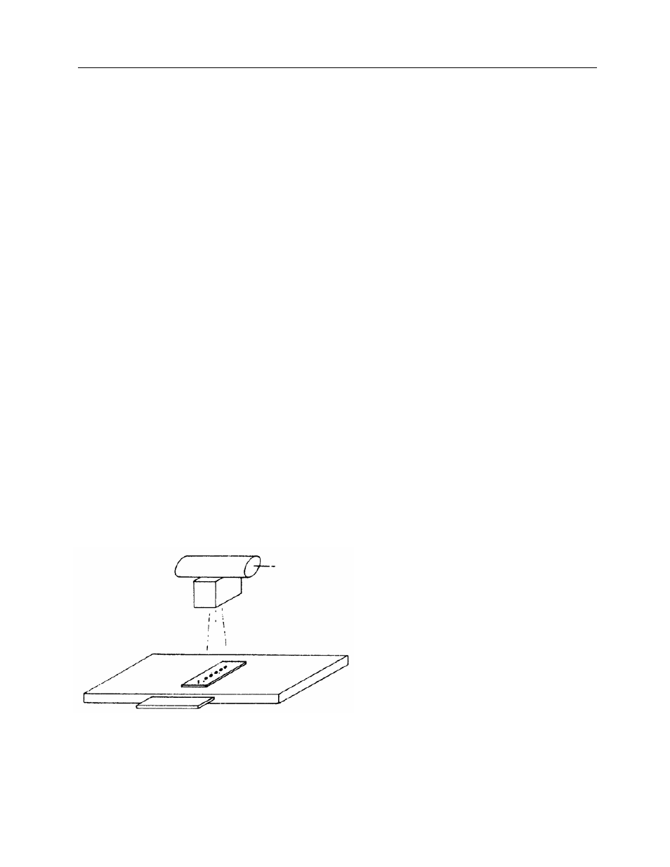
Position the Grid Alignment Test Tool on top of the table so that its long dimension is perpendicular to the
grid lines (long dimension of the tube). Center the middle hole of the tool in the optical crosshairs of the
collimator light field. The three small marking holes should be pointed toward the front of the table (Figure
2-1). Tape the Grid Alignment Tool to the table so it does not move for the duration of the test.
Collimate to approximately a square just smaller than the width of the test tool. Place the small lead
blockers on the tools so only the middle (and the two small holes on either side of it) are irradiated and all
other large holes are covered. Make an exposure at approximately 60 kVp and 2-4/mAs using the lowest
available mA settings to obtain an optical density in the middle hole of between 1. 0 and 2.0 on the
developed film. For longer exposures copper strips (0.040" thick are available from Fluke Biomedical,
Radiation Management Services) can be placed over the holes. Repeat the exposure so that by moving
the tube laterally each of the five large holes is irradiated while centered in the crosshairs. It is not critical
to set the middle hole of the test tool under the exact center of the optical crosshairs for the initial
positioning. However, it is important that the hole is in a uniform part of the x-ray beam and not in the
edge of the field falloff. It is also important that whatever collimator marking is initially aligned over the
middle hole, all hole exposures are made with that same collimator marking aligned over the hole
irradiated. This insures that the x-ray tube is actually moved laterally one inch between adjacent hole
exposures. Be sure to use the same technique settings at each position and do not forget to move the
small lead blockers each time to cover the four large holes not being irradiated. Also be sure to irradiate
the small marking holes on the test tool to insure the tool orientation is recorded on the film.
Figure 2-1. Diagram Showing Arrangement of Grid Alignment Test Tool for Checking Grid Alignment