Fluke Biomedical 84-340 User Manual
Page 7
Introduction
Description
1
1-3
Figure 1-3
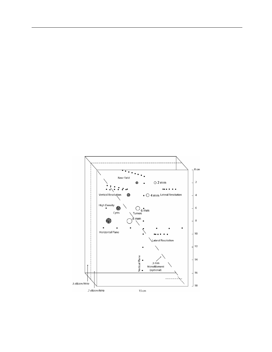
Vertical Plane Target
A group of .3 mm parallel wires are positioned 2 cm apart down the center of the phantom in a vertical
plane (Figure 1-4). When scanned from the top this target enables measurement of vertical linearity,
depth calibration and gain as a function of depth.
Horizontal Plane Target
A group of .3mm parallel wires are positioned 2 cm apart in a horizontal plane at mid-depth in the
phantom for calibration and linearity measurements (Figure 1-4).
Low Scatter Targets
A diagonal row of four cylinders having little or no scatter are provided in the phantom to test a machine's
ability to image cyst like structures of varying size and depth in two different backgrounds. Cylinder
diameters range from 8 mm at a depth of 8 cm to 2 mm at a depth of 2 cm (see Figure 1-4).
High Scatter Targets
A diagonal row of cylinders having scatter properties discernibly higher than the background are available
to test a machine's ability to image tumor like structures of varying size and depth in two different
backgrounds. Cylinder diameters range from 8 mm at a depth of 8 cm to 2 mm at a depth of 2 cm (see
Figure 1-4).
Figure 1-4