Chapter 2 installation instructions, Front panel connector: cn34, Hdd-led connector – Foxconn 865A05-G-6ELS User Manual
Page 20: Reset switch, Pwr-led indicator
14
Chapter 2 Installation Instructions
865A05 G/P/PE/GV User Manual
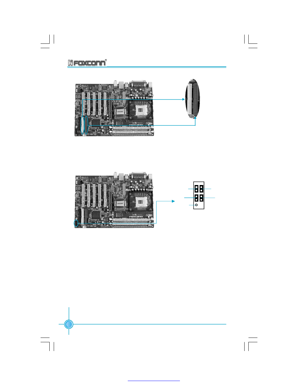
PIDE
SIDE
Front Panel Connector: CN34
This motherboard includes one connector for connecting the front panel switch
and LED indicator.
HDD-LED Connector
Attach the connector to the HDD-LED on the front panel of the case; the LED will
flash while the HDD is in operation.
Reset Switch
Attach the connector to the Reset switch on the front panel of the case; the system
will restart when the switch is pressed.
PWR-LED indicator
Attach the connector to the power LED on the front panel of the case. The Power
LED indicates the power supply status, and will be lit during normal system
operation. The Power LED will blink while the system is in the S1 mode, and will
be turned off when the system is in either S5 mode.
NC
HD-LED
RE SE T
PW R-LED
PW R-SW
+
-
+
-
9 10
1 2
PDF created with pdfFactory Pro trial version