Chapter 2 installation instructions – Foxconn 648FX7MF-RS User Manual
Page 26
Chapter 2 Installation Instructions
18
661FX7MF/648FX7MF/648C7MF Series User Manual
Front Panel Connector: F_P1
This motherboard includes one connector for connecting the front panel switch
and LED indicators.
Hard Disk LED Connector (IDE_LED)
The connector connects to the case’s IDE indicator LED indicating the activity
status of IDE hard disk.
Reset Switch (RESET)
Attach the connector to the Reset switch on the front panel of the case; the
system will restart when the switch is pressed.
Power LED Connector (PLED)
Attach the connector to the power LED on the front panel of the case. The Power
LED indicates the system’s status. When the system is in S0 status, the LED is
on. When the system is in S1 status, the LED is blink; When the system is in S3,
S4, S5 status, the LED is off.
FP1
Power Swith Connector (PWRBTN#)
Attach the connector to the power button of the
case. Pushing this switch allows the system
to be turned on and off rather than using the
power supply button.
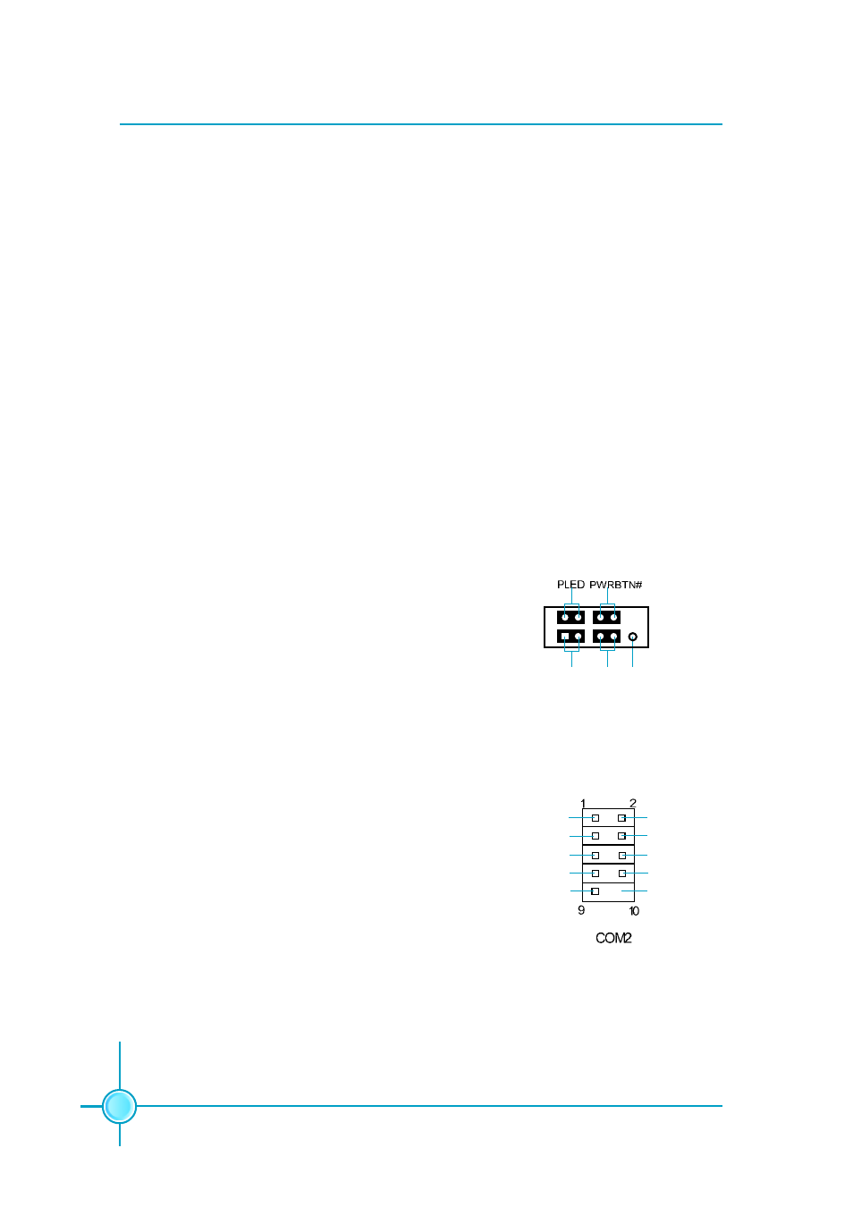
COM2 Connector: COM2
This connector accommodates a second serial
port using an optional serial port bracket. Con-
nect the bracket cable to this connector then in-
stall the bracket into a slot opening at the back of
the system chassis.
NC
IDE_LED R E S E T
1 + -
+ -
DSR
D T R
SIN
C T S
R T S
SOUT
RLSD
RI
GND
N A