Bike/utility lift, Raise object, Lower object – Harken 7800 1-Point Bike/Utility Lift - 45 lb User Manual
Page 2
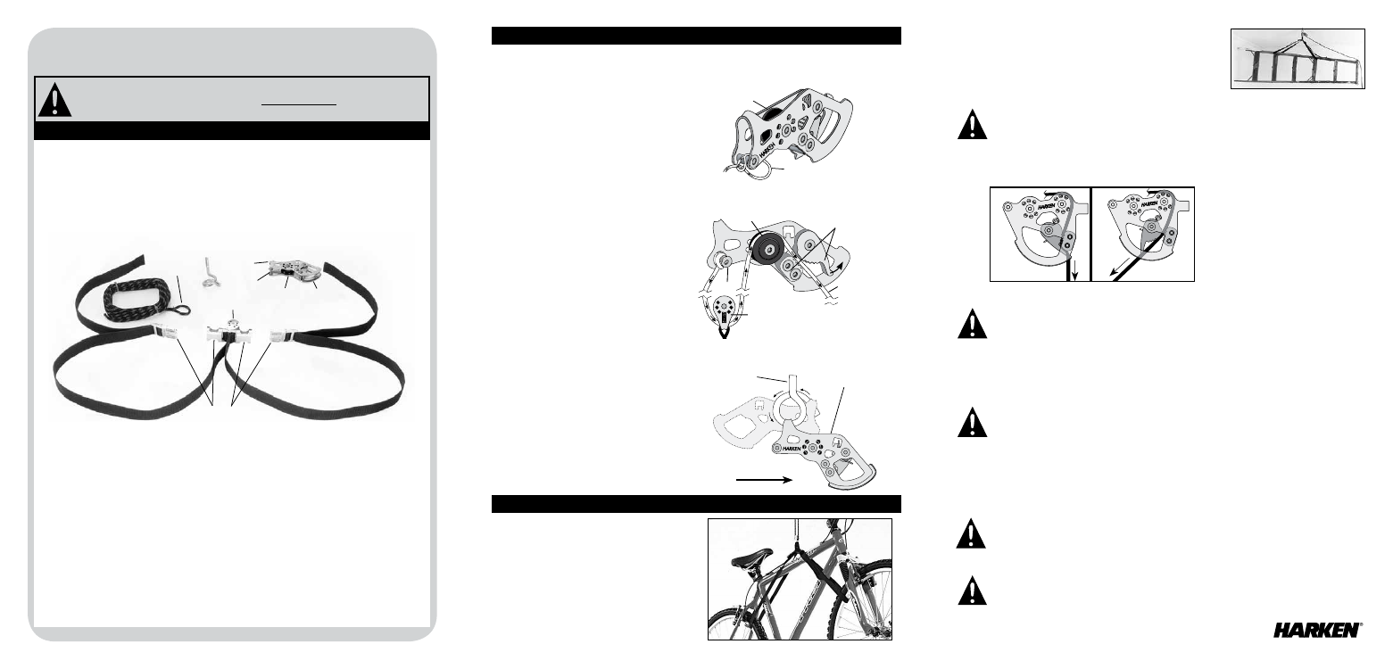
Rear of bike
Pigtail
lag screw
Top of self-locking cleat
Fig. 3: Strap assembly with lower pulley
Other items:
Thread buckles around and/or through a solid
connection point (i.e. rungs of a ladder). Fasten buckles and
adjust strap lengths to balance load.
BIKE/UTILITY LIFT
Installation/Operating Instructions
Electric/hand drill
Stepladder
Drill bit
5.5 mm (7/32")
Safety glasses
Stud finder
(available at a building supply store).
Please refer to photo/diagrams for terms. Unpack all parts and completely unwind rope.
N15W24983 Bluemound Rd.
•
Pewaukee, Wisconsin 53072 USA
•
Tel: 262-701-5780
Web: www.harken.com/hoister
•
Email: [email protected]
Sewn loop
Rope
Pigtail
lag screw
Self-locking
cleat
Strap assembly
Lower
pulley
Upper
pulley
Post
Top
Buckles
Locking
mechanism
Attach Lower Pulley
Pass rope through lower pulley on strap
assembly. Thread rope back between post
and upper pulley. Hold locking mechanism
open. Feed rope around upper pulley, and
out through locking mechanism.
Fig. 2: Self-locking cleat (cutaway)
post
Upper pulley
Locking mechanism
Lower pulley
Control rope
Printed in USA 4900/10-14
Post
Upper pulley
Sewn loop
Fig. 1: Self-locking cleat
Attach Rope to Cleat
Start at bottom of self-locking cleat. Pass sewn
loop between post and upper pulley, and around
post. Allow sewn loop to protrude slightly from
cleat. Thread rope through loop. Tighten.
The Harken Hoister is covered by a 5-year Limited Warranty. The warranty covers the Hoister
pulleys when used in accordance with installation instructions and weight limits specified
in instructions, but does not include rope, straps, or buckles. Harken is not responsible for
proper and safe installation of the Hoister in various overhead materials. Consult a professional
contractor to assure safe installation. CONSEQUENTIAL AND INCIDENTAL DAMAGES ARE NOT
RECOVERABLE UNDER THIS WARRANTY. Some states do not allow the exclusion or limitation
of incidental damages, so the above limitation or exclusion may not apply.
Max lifting load: 20 kg (45 lb)
Max vertical lift: 2.4 m (8')
Min lifting load: 4.5 kg (10 lb)
Mechanical advantage: 2:1
Specifications
Tools Needed
Installation
WARNING! Strictly follow all instructions to avoid an accident, damage
to property, personal injury, or death. See www.harken.com for additional
safety information.
Attach bike/other items
Place item directly under lifting
system and unbuckle strap assembly.
Bicycles:
Thread one buckle through
rear wheel and frame. Fasten. Thread other
buckle through front wheel (behind fork),
and around frame. Fasten.
Raise Object
DIAGRAM 1. Locked (left): Single black/red
hoisting rope (F) pointed straight down
locks cleat. Open (right): Angled rope
opens cleat.
Hoist in a series of pulls. Pull single black/red hoisting rope (F) straight down. When rope points
down, cleat will lock rope. You can release it. Repeat until object is at desired height.
LOCKED:
Rope (F) down
OPEN:
Rope (F) angled
Securely grip rope, apply tension, and angle it away from object. Bring arm up to let rope out,
then back toward object to lock rope. Repeat until object is at desired height
.
Lower Object
WARNING! When operating system, make sure area below object is clear of persons.
If object comes down too quickly, this can cause an accident, damage to property,
personal injury, or death.
WARNING! Hang coiled rope where it will not accidentally snag on persons or vehicle.
Keep coiled rope out of reach of children. Damage or injury can result if rope is angled
away from wall with some tension; object can come down quickly which can cause an
accident, damage to property, personal injury, or death.
WARNING! Stop pulling as soon as object contacts ceiling or webbing strap knots
stop at pulley (D). Damage or injury can result from forcing the system. If in doubt,
stop hoisting. Allow cleat to lock by angling rope down. Stand back to see if object
is raised to the maximum, or if something is jamming rope or object
.
WARNING! Do not raise or lower object with anyone standing underneath. Keep area
below Hoister clear. Do not use this product for human suspension. If components fail,
it can cause an accident, damage to property, personal injury, or death.
Warranty
NEVER USE TO LIFT A PERSON
CAUTION! Avoid injury! Do not let rope slip through hands. Angle rope to object to lock rope.
Tip: Use gloves to protect hands.
With object in raised position, make sure single black/red hoisting rope (F) is securely locked in
cleat with rope pointed down (diagram 1). Coil loose rope end. Hang coiled rope for storage when
system is not in use.
Install Hoister
Use stud finder to locate trusses/rafters. If not
visible, follow stud finder instructions. Drill a
5.5 mm (
7
/
32
") hole into truss/rafter above
balance point of load. Screw pigtail lag screw
threads all the way into truss/rafter. Orient lag
screw so end of rope points toward rear of bike.
Slip top of self-locking cleat over end of pigtail
lag screw. Always wear safety glasses!
Parts List
1 self-locking cleat
1 strap assembly (lower pulley and buckles)
1 4.8 mm (21 3/16") rope with sewn loop
1 pigtail lag screw
Part No.
77525
HCP1458
HCP2063
HCP1444
4900 10/14
Operation