Inductive ihs system, Lhf power supply, Gas console – Hypertherm HT2000LHF Product Configuration User Manual
Page 13: Water muffler system, Timer/counter ar-h, Manifold, Computer interface
ORDERING PROCEDURE
2-2
HySpeed HT2000LHF
Product Configuration Manual
2
Inductive
IHS
System
IHS
Pressure
Regulator
Assembly
Work table
Workpiece
1X6
1X7
8X1
1X10
1X5
1X4
LHF
Power
Supply
O
2
in
Gas
Console
Shield in
Argon/Hydrogen
in
1X2
3X1
1X3
1X9
Programmable
Remote
V/C Control
Console
5X2
5X1
Water Muffler
System
1
21
20
a
20
21
2
31
20
2
4
3
23
22
5
26
27
28
19
29
30
12
13
14
15
16
17
18
11X1
To Second HySpeed
LHF Power Supply
Timer/Counter
Ar-H
2
Manifold
N
2
in
8X2
8X3
14X1
Valve Cluster
1X1
Digital
Remote
V/C Control
Console
5X1
Remote
Current Control
Console
15X1
1X4
1X7
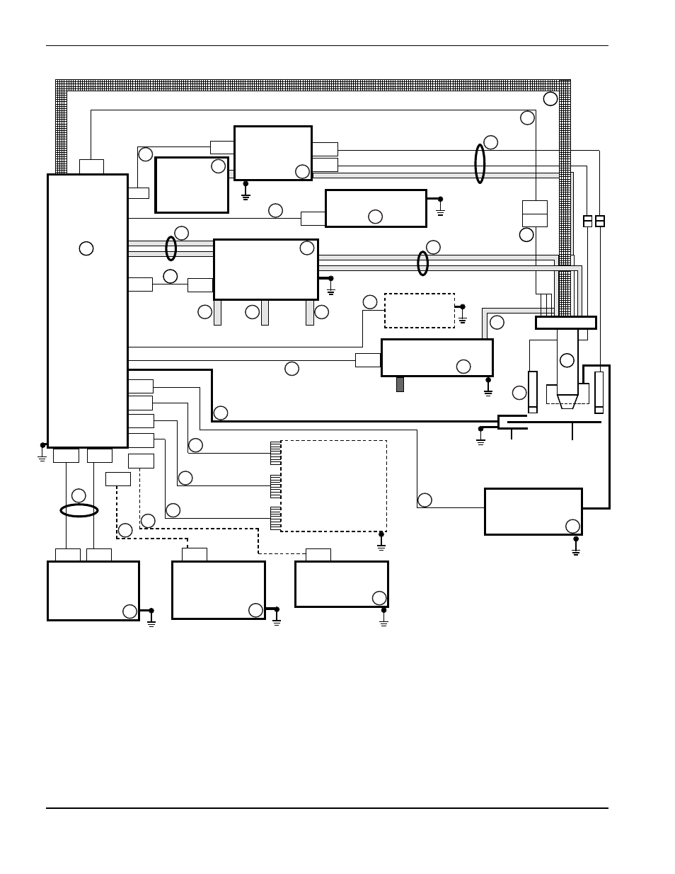
1
LHF Power Supply (PS)
2
Torch Assembly with Valve Cluster
3
Shielded Leads Between Power Supply and Torch
4
Cable Between Power Supply and Torch Valve Cluster
5
Gas Console
6
Leads Between Gas Console and Torch
7
Shield Gas Hose Set Between Gas Console and Power Supply
8
Cable Between Gas Console and Power Supply
9
Programmable Remote Voltage & Current Control Console
10
Digital Remote Voltage & Current Control Console
11
Remote Current Control Console
12
Cables Between PS and Programmable Remote
13
Cable Between PS and Digital Remote
14 Cable Between PS and Remote Current
15
Cable Between PS and Machine Computer V/C Interface
16
Cable Between PS and Machine Computer I/O Interface
17
Cable Between PS and Remote Control Panel Interface
18
Cable Between PS and Work Table
19
Hold Cable Between Power Supplies in Multi-Torch Systems
20
Inductive IHS System
20a IHS Pressure Regulator Assembly
21
Inductive IHS Lead Set
22
Timer/Counter
23
Cable Between Timer/Counter and Power Supply
24
Water Muffler System
25
Cable Between Water Muffler Pump and Power Supply
26
Hose Between Nitrogen Supply and Gas Console
27
Hose Between Oxygen Supply and Gas Console
28
Hose Between Shield Gas Supply and Gas Console
29
Argon-Hydrogen Manifold
30
Cable Between Argon-Hydrogen Manifold and Power Supply
31
Hose Between Argon-Hydrogen Manifold and Torch
4X1
4X1
HT2000 LHF Block Diagram
9
10
11
Computer
Interface
Customer Supplied
25
24
6
7
3