IBASE MB837-D25 User Manual
Page 20
INSTALLATIONS
14
MB837-D25 / MB837-D25-R User’s Manual
J11: DC Power Jack (+12V only)
Note: Do not connect J9 and J11 at the same time.
LED1, LED2, LED3 & LED4: LAN Port Link, Active LEDs
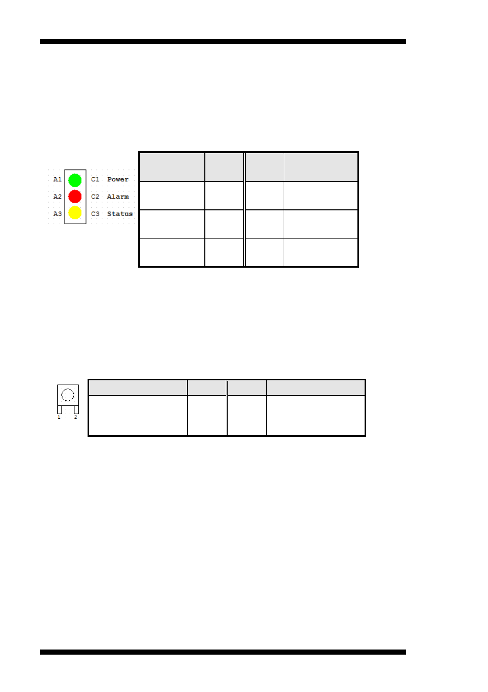
LED5: Power, Alarm & Status LEDs
Signal
Name
Pin #
Pin #
Signal
Name
PWR
LED+
A1
C1
PWR LED-
ALARM
LED+
A2
C2
SIO GPIO55
STATUS
LED+
A3
C3
SIO
GPIO56
Index port: 4E
Data port: 4F
Device: 08
30h bit1 = 1
E0h bit5, bit6 = 0
E1h bit5, bit6 (Control pin)
SW3: Software Reset Button
Signal Name
Pin #
Pin #
Signal Name
GND
1
2
Intel NM10 PCH
GPIO7
IO Base:
Read IO 0x500 and set bit 7 to “1” (Enabled GPIO function)
Read IO 0x504 and set bit 7 to “1” (GPIO act as GPI )
Read IO 0x50C and check the bit 7 (Control Pin)
Note: SW3 is controlled by GPIO only.
SW2: Power Switch
JP3: Mini-PCI Connector