Signal description – IBASE IOPS-76 User Manual
Page 13
13
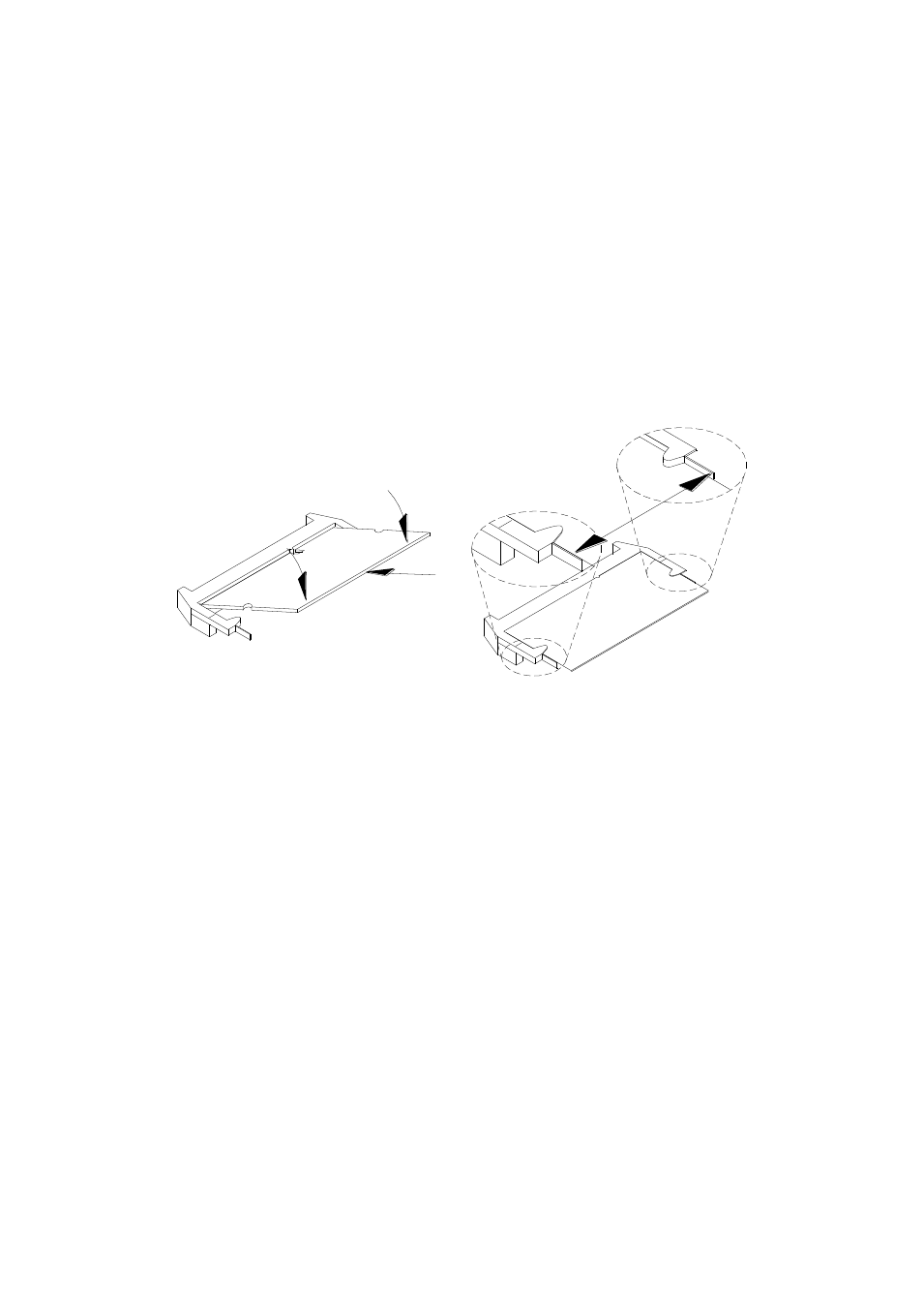
following steps:
1.
Hold the DDR3 module so that the key of the DDR3 module aligns with that on
the memory slot. Insert the module into the socket at a slight angle
(approximately 30 degrees). Note that the socket and module are both keyed,
which means that the module can be installed only in one direction.
2.
To seat the memory module into the socket, apply firm and even pressure to
each end of the module until you feel it slip down into the socket.
3.
With the module properly seated in the socket, rotate the module downward.
Continue pressing downward until the clips at each end lock into position.
4.
To remove the DDR3 module, press the clips with both hands.
Signal Description
This section provides a detailed description of each signal passing thru the JAE
connector. The signals are arranged in functional groups according to their associated
interface.
The “#” symbol at the end of the signal name indicates that the active or asserted
state occurs when the signal is at a low voltage level. When “#” is not present, the
signal is asserted when at the high voltage level.
The following notations are used to describe the signal type with regards to the
pluggable board:
I Input Pin
O Output Pin
OC Open Collector Output Pin.
The “Type” for each signal is indicative of the functional operating mode of the signal.