Components, Front view – IBASE FWA7304G User Manual
Page 7
7
Components
Front View
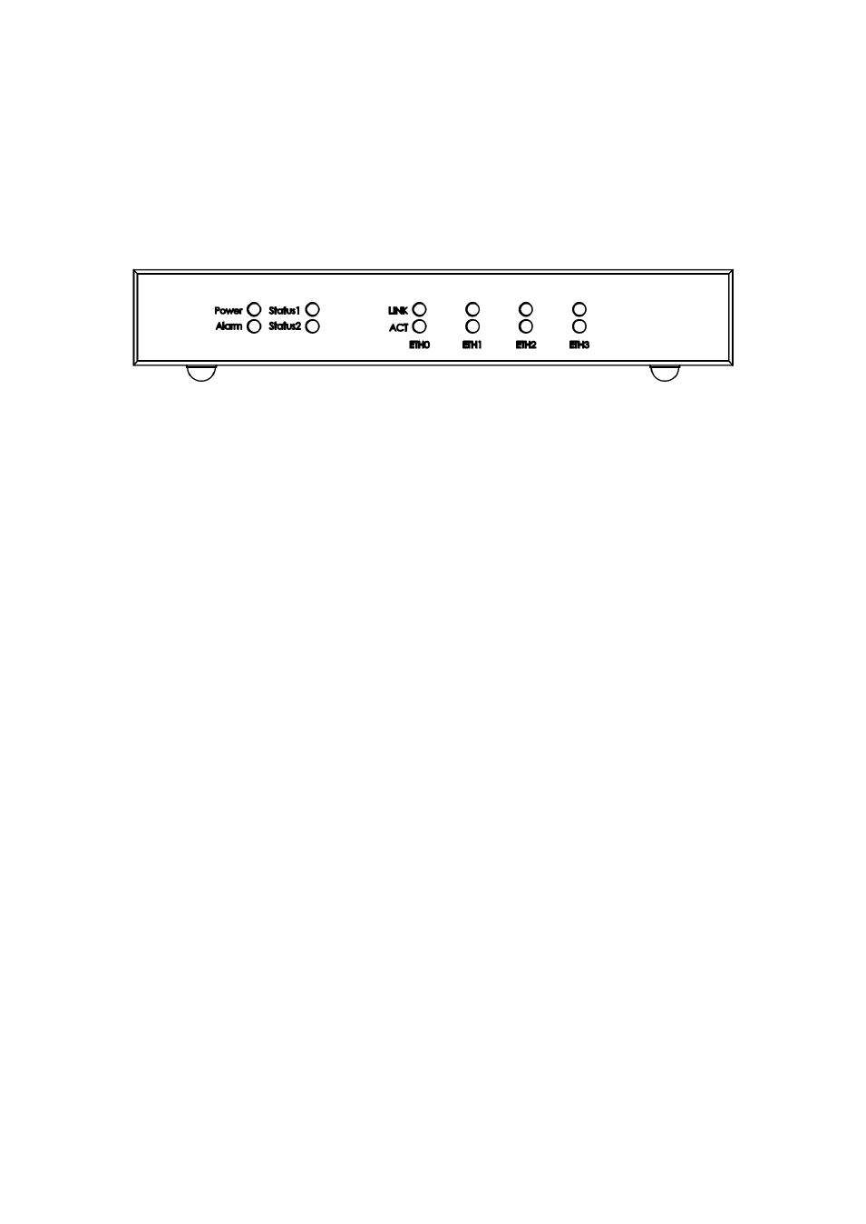
Refer to the diagram below to identify the components on this side of the system.
Power
The power LED illuminated when system been power on.
Alarm
There are user programmable indicators. Each indicator can be program to
specify status indicator. The detail programming method please refer M/B user
manual.
Status1 & Status2
There are user programmable indicators. Each indicator can be program to
specify status indicator. The detail programming method please refer M/B user
manual.
LINK
The orange color shows corresponding LAN port connected with Giga-speed.
The Green color shows corresponding LAN port connected with 100-Base-T
speed.
ACT
The LED illuminated when corresponding LAN port transmitted or received data.
ETH0~ETH3
Corresponding to each LAN port status indicators.