IBASE IBD189 User Manual
IBASE Hardware
IBD189
CAN BUS CARD
PCI Express Mini Card V1.2
User guide 1.0
IBD189 and PK1-79 Mechanical Drawing
IBD 189 x 1 and PK1-79 x 2
Setting the Jumpers
SW1: Programmable Firmware Upgrade Setting
Default: Normal Mode, Pin 1,2 OFF
SW1-1P
SW1-2P
F/W Upgrade Mode
OFF
OFF
Normal Mode*
ON
OFF
DFU Mode
*Default
Connectors pin definition
CAN1, CAN2: CAN BUS Connector
1X4_1.25mm_Right Angle_Male_Wafer (E-CALL 0110-2620040, Mating connector:
Molex 53048-0410)
Pin #
Signal Name
1
DATA H
2
Ground
3
DATA L
4
Ground
J3: JTAG (factory use only)
2X4_2.0mm_Straight_Male_Pin Header (E-CALL 0196-01-251-080)
Signal Name
Pin # Pin #
Signal Name
+3.3V
1
2
GND
TRST
3
4
TCLK
TDI
5
6
TDO
TMS
7
8
Reset
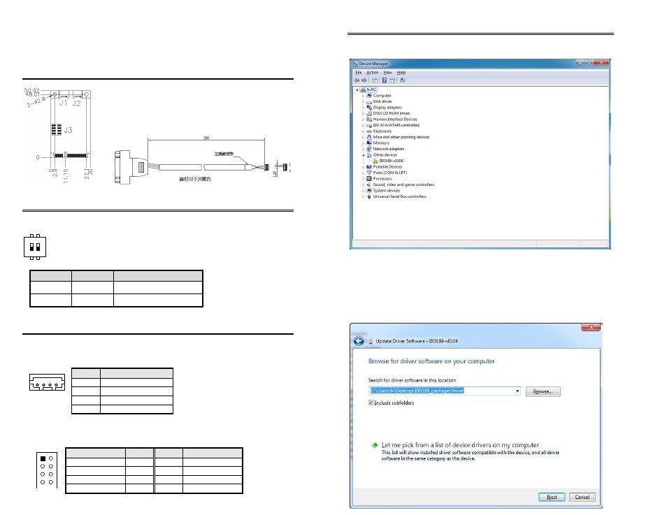
Mini PCI-E CAN Bus Card Driver Installation
1. In the Windows OS, go to the Computer Management screen. In the ‘Other
devices’ as shown, right click the “PCI Serial Port” Properties.
2. In the PCI Serial Port Properties screen, click Update Driver.
3. In the Hardware Update Wizard screen, select “No, not this time” and click
Next to continue.
4. Select “Install from a list or specific location (Advanced), and click
Next to continue.
5. Choose “search” and “installation” options, click the checkbox of “Include
this location in the search”, and click Browse to find the driver’s path in the
CD provided or enter the path directly -
\IBD189_package\Driver\IBD189.inf
1
ON
2
2
1
4 3
4
1
2
8
6
4
1
7
5
3