Pt3000_p2, Assembly instruction, Pt3000 – ikan PT3000 User Manual
Page 3
3903 Stoney Brook Dr. Houston TX 77063 | +1.713.272.8822 | www.ikancorp.com | [email protected] | © 2009 ikan Corporation. All right reserved.
ASSEMBLY INSTRUCTION
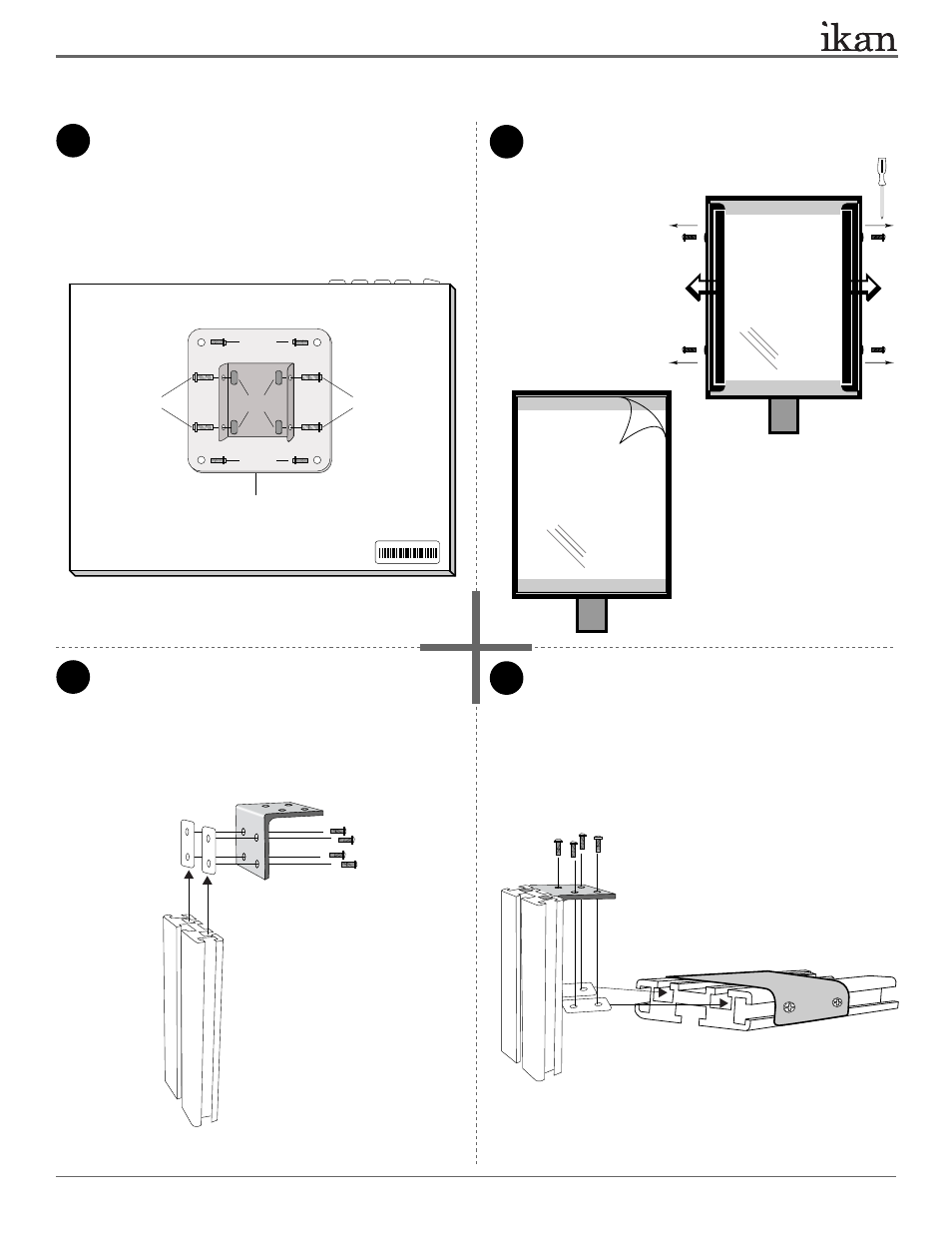
1
3
4
2
Attach the 100mm Mounting Bracket (Part K) to the back
of the 15” monitor using 4 x Short Phillip’s head screws
(Part H). The two flaps of Part K should be perpendicular
to the monitor control buttons.
Attach 4 x T-slot Nuts (Part D) and 4 x Long Phillips Head
Screws (Part G) as shown on the diagram.
Attach the 20” T-slot with Metal Bracket (Part P) to the
assembled parts. You will use 2 x T-plates (Part C) and
4 x Long Phillips Head screws (Part G) to do so. Make
sure to evenly tighten all screws in this assembly.
Remove protective film from Part-L.
> Unscrew the 4 small screws
that are pre-placed in Part L.
> Remove glass holding tabs on
both sides.
> Peel the protective film away.
> Re-install the teleprompter glass back
into the metal frame.
Part-L
PT3000
15” TELEPROMPTER
Part-I
Part-M
Part-P
Attach Short L-Bracket (Part I) to 8” T-slot (Part M)
using 2 x T-plates (Part C) and 4 x Long Phillips head
screws (Part G). Refer to illustration below for configu-
ration. The Short L-Bracket’s (Part I) top half should be
flush with the edge of the 8” T-slot (Part M).
Part-G
Part-G
Part-C
Part-C
PT3000
Rear view of 15” monitor
Part-K
Part-D
Part-G
Part-G
Part-H
Part-H
2 of 10