InSinkErator Evolution 200 User Manual
Food waste disposer installation and use manual
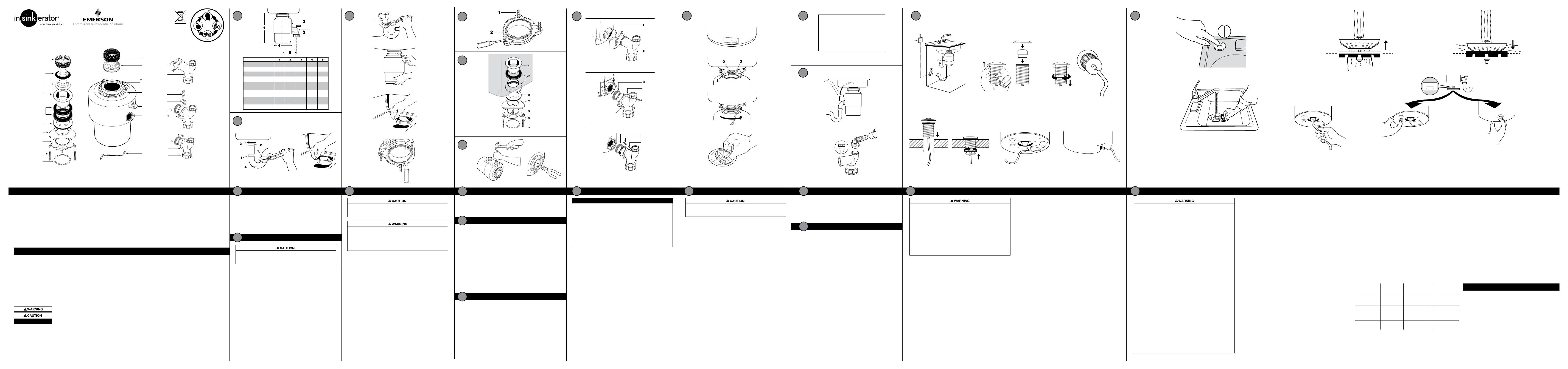
DISCHARGE TUBE INSTALLATION (EVOLUTION 200 AND EVOLUTION 100)
Place discharge tube (2) into Anti-Vibration Tailpipe Mount
™
. Secure with spring
type hose clamp (1). (See Figure 7.1)
DISCHARGE TUBE INSTALLATION (MODELS 65+, 60+, 55+, 50+, 45+)
1. Install two square nuts (3) in pockets of discharge outlet. (See Figure 7.2)
2. Place metal flange (5) over discharge tube (7). Insert rubber gasket (4) with
gasket lip facing the metal flange into discharge tube. (See Figure 7.2)
3. Secure metal flange and discharge tube to disposer with two 13 mm bolts (6).
DISCHARGE TUBE INSTALLATION (LC-50)
1. Place metal flange (10) over discharge tube (11). (See Figure 7.3)
2. Insert rubber gasket (8) with the gasket lip facing the metal flange
into discharge tube (gasket may be pre-fitted in discharge tube).
Secure metal flange and discharge tube to disposer with one
19 mm bolt (9) (Gasket will hold in place).
3.1
3.2
3.3
3.4
3.1
3.2
3.3
3.4
4.1
www.insinkerator.com
©2013 InSinkErator, a business unit of
Emerson Electric Co. All Rights Reserved.
5.1
2.1
2.2
Food waste disposers can provide an environmentally responsible alternative to transporting food waste to landfills. And they can help reduce greenhouse gas
emissions. At capable wastewater treatment plants, food waste can be recycled to produce renewable energy. Additionally, capable wastewater treatment plants
can process food waste into fertilizer. (Check the plant in your area).
Read through the entire installation manual before installing the disposer. Determine which of the tools, materials, and accessories you will need before you begin.
Make sure you have all necessary disposer parts before installing the disposer.
NOTE: The Evolution models grind much finer than any other disposer. For this reason you may notice that it takes a little longer to grind some food waste. Due to
the Evolution 200 model’s microprocessor, users will experience a fractional second delay when starting on all Evolution 200 models. This is completely normal.
NOTE: Make sure that the installation of this appliance is allowed by the authorities.
TOOLS & MATERIALS YOU WILL NEED:
Slotted Screwdriver, Adjustable Pliers, Safety Glasses
TOOLS, MATERIALS, AND ACCESSORIES YOU MAY NEED:
Phillips Screwdriver, Drain Auger, 9.5 mm Electrical Clamp, 38 mm Drain Trap, 33 mm Hole Drill, Hammer, Hacksaw, Water Hose Clamp, Pipe Wrench, Copper Earth
Wire, Dishwasher Drain Connection Kit, Electrical On/Off Switch, Drain Tube Extension
1. Disposer height.
2. Distance from bottom of sink bowl to centerline of discharge outlet. (Add
12 mm when stainless steel sink is used.)
3. Distance from centerline of the discharge outlet to end of discharge tube.
4. Disposer width.
5. Distance from disposer vertical centerline to centerline of trap connection.
To properly drain and prevent standing water in the disposer, the waste pipe
entering the wall must be lower than the disposer discharge outlet.
DISCONNECT SINK DRAIN
1. Loosen nuts (1) at top of trap (4) with pipe wrench. Remove trap.
(See Figure 2.1)
2. Loosen nut (2) at top of extension pipe. Remove extension pipe.
3. Remove nut (3) at base of sink flange.
4. Push strainer up through sink hole and remove it. (See Figure 2.2)
5. Clean sink flange area of any putty or other debris.
NOTE: The sink hole may have to be enlarged to accept the disposer
sink flange. Sink hole enlargement tools are available from your
InSinkErator dealer.
CLEAN SINK DRAIN
Failure to clean sink waste pipe line may result in waste pipe blockage.
With drain auger, clear away all hardened waste material in horizontal drain
line running from drain trap to main pipe.
When installing in new construction, cleaning the sink waste pipe line is
not necessary.
IF REPLACING AN EXISTING DISPOSER,
CONTINUE WITH INSTRUCTION 3.
IF THIS IS A FIRST TIME INSTALLATION,
SKIP AHEAD TO INSTRUCTION 4.
1. Turn mounting assembly over (see Figure 4.1) and loosen three mounting
screws (1) until you can access snap ring (2).
2. Use screwdriver to pry snap ring off of sink flange. Mounting assembly can
now be disassembled.
Reference Figure 5.1.
1. Place one of two rubber gaskets (2) under sink flange (1). Ensure sink hole
area is clear of debris and place sink flange/gasket into sink hole. You may
wish to place a weighted object in the sink to hold the sink flange in place.
(Place a towel under object to prevent scratching.)
2. Working from under the sink, slip second rubber gasket (2), fiber gasket
(optional) (3) and metal backup flange (4) (flat side up) over the sink flange.
Holding second rubber gasket, fiber gasket (optional) and metal backup
flange in place, slip mounting ring (5) over sink flange so it seats against
backup flange.
3. With the rubber gasket, fiber gasket (optional), backup flange, and
mounting ring tight against sink bottom, slide snap ring (7) onto sink
flange until it pops into groove on flange.
4. Tighten three mounting screws (6) up to sink until mounting assembly is
seated tightly and evenly against sink.
IF YOU ARE NOT CONNECTING A DISHWASHER
TO DISPOSER, SKIP AHEAD TO INSTRUCTION 7.
FOOD WASTE DISPOSER INSTALLATION AND USE MANUAL
FOOD WASTE DISPOSER INSTALLATION AND USE MANUAL
CHECK INSTALLATION DIMENSIONS
1
DISCONNECT AND CLEAN SINK DRAIN
2
DISASSEMBLE NEW DISPOSER
MOUNTING ASSEMBLY
4
PARTS LIST (May vary depending on model)
220-240V, 50/60Hz
for UK/Hong Kong/Ireland/Saudi Arabia
1
4
3
6
2
5
77
34
8 R
E
V A
EVOLUTION MODELS
45+, 50+, 55+, 60+, 65+ MODELS
LC-50
7.3
7.2
7.1
5
6
6
7
9
8
10
11
ATTACH DISCHARGE TUBE TO WASTE DRAIN PIPE
7
7
Warning indicates a potentially hazardous situation which, if not avoided, could result in death or serious injury.
Caution indicates a hazardous situation which, if not avoided, could result in minor or moderate injury.
Notice is used to address practices not related to personal injury.
PERSONAL INJURY
Wearing safety glasses is recommended during the installation of the
food waste disposer.
PROPERTY DAMAGE
• All Evolution 200 and Evolution 100 models must be connected to
the supplied tailpipe with the supplied spring type hose clamp (See
Figure 7.1). Failure to use the supplied tubes and spring type hose
clamp will void the guarantee and possibly cause premature failure of
the Anti-Vibration Tailpipe Mount
™
.
• Do not use plumber’s putty on any other disposer connection. Do not
use thread sealants or pipe dope. These may harm disposer and cause
property damage.
• Regularly inspect disposer and plumbing fittings for water leaks,
as water leaks can cause property damage. Manufacturer cannot
be held responsible for property damage as a result of water leaks.
NOTICE
NOTICE
PERSONAL INJURY
To avoid personal injury, do not position your head or body under
disposer; the unit could fall during installation.
ELECTRICAL SHOCK
• To avoid electrical shock, disconnect power before removing any existing
disposer. Turn off electrical power at fuse box or circuit breaker or if
equipped unplug disposer electrical power plug from wall outlet.
• Improper connection of equipment earth (grounded) conductor can
result in electric shock.
1. If your disposer is equipped with an electric plug and cord connection,
unplug power plug from electrical wall outlet.
If your disposer is not equipped with an electrical plug and cord
connection, contact an electrician to disconnect the old disposer plus
install an earth (grounded) electrical wall outlet for the new disposer
connection that must be compliant to all local electrical codes.
2. Disconnect drain trap from disposer waste discharge tube with
adjustable pliers (see Figure 3.1). Also disconnect dishwasher drain
connection, if applicable.
3. Support disposer with one hand and insert end of wrenchette or
screwdriver into right side of one mounting lug on lower mounting ring
(see Figure 3.2). Lift disposer slightly and remove from mounting by
pushing or pulling wrenchette or screwdriver to left (disposer may be
heavy; provide support).
4. Loosen three mounting screws, pry snap ring off with screwdriver,
and remove old mounting assembly (see Figure 3.3). Some mounting
assembly removal requires additional tools.
5. Push old sink flange up through sink hole (see Figure 3.4).
REMOVE EXISTING DISPOSER
3
English only (UK, Hong Kong, Ireland, and Saudi Arabia)
6.1
6.2
Wastewater from a dishwasher can be plumbed into the disposer through
the inlet access on the upper part of the disposer. There is a plug on the
inside of the inlet tube on all models. Once removed, the knockout plug
cannot be replaced.
NOTE: If the dishwasher connection is made without removing the plug,
the dishwasher may overflow. (Connections must comply with local
plumbing codes.)
REMOVE KNOCKOUT PLUG
1. Lay disposer on its side and insert slotted screwdriver into dishwasher inlet
so tip rests on outer edge of knockout plug.
2. Tap end of screwdriver handle with hammer until molded plug breaks
loose. (See Figure 6.1)
3. Remove loose knockout plug from inside disposer. (See Figure 6.2)
6
REMOVAL OF KNOCKOUT PLUG
FOR DISHWASHER CONNECTION
5
ATTACH UPPER MOUNTING ASSEMBLY TO SINK
11.1
11.3
11.5
11.6
11.2
11.4
33 mm
If you have a sink overflow, it should be connected to the overflow inlet on
the tailpipe (see Figure 10.1).
To connect the overflow, remove the plug in the tailpipe by unscrewing the
overflow connector cap (see Figure 10.2).
Connect the hose from the dishwasher to the disposer inlet using a
dishwasher drain connection kit with a hose clamp (not provided).
NOTE: In the UK, waste trap kit, which does not include the sink overflow kit,
is available from your local InSinkErator dealer.
AIR SWITCH (EVOLUTION 200, EVOLUTION 100, MODELS 65+,
60+,55+ A/S, 50+ A/S AND 45+ A/S)
The Evolution 200, Evolution 100, Model 65+, Model 60+, Model 55+ A/S,
Model 50+ A/S and Model 45+ A/S disposers include a built-in air switch
(Brushed Nickel and Chrome finishes). An air switch activates/turns off the
unit by sending a pulse of air to the control box.
AIR SWITCH INSTALLATION
The air switch includes two different button finishes. If you wish to change the
button finish (optional), simply pry off the existing button and snap the other
button finish onto the bellows. (See Figure 11.2)
1. Drill a 33 mm wide hole into the kitchen work top, or the corner of the sink
unit, at the most convenient point for use. Some sink units may already
have a suitable hole in them which can be exposed by removing the cap.
2. Remove the nut from the push button bellows, while keeping the stainless
steel washer and rubber gasket in place. Push one end of the PVC tubing
onto the spout of the push button bellows, feed the other end of the tube
through the hole in the work top and through the nut underneath the work
top. (See Figure 11.3)
3. Fit the push button bellows in the hole and then thread the nut underneath
the work top until it is hand tight.
Do not use a wrench to tighten the nut.
(See Figure 11.4)
4. Take the other end of the air tube and firmly push it over the spout of the
air switch, which is located on the underside of the waste disposer on
Evolution 200 and Evolution 100 models (see Figure 11.5), or on the side
of the disposer on Models 65+, 60+, 55+ A/S, 50+ A/S or 45+ A/S
(see Figure 11.6).
DISABLING THE AIR SWITCH
The air switch can be disabled if wall switch operation is preferred.
The disposer is shipped with the switch in the “off ” position.
1. Push one end of the PVC tubing provided onto the spout of the push
button bellows. (See Figure 11.3)
2. Take the other end of the air tube and firmly push it over the spout of the
air switch, which is located on the underside of the waste disposer on
Evolution 200 and Evolution 100 models (see Figure 11.5), or on the side
of the disposer on Model 65+, 60+, 55+ A/S, 50+ A/S, or 45+ A/S
(see Figure 11.6).
3. Depress the air switch one time until you hear the switch “click.” Remove
and discard the push button bellows and PVC tubing. The disposer may
now be activated by a wall switch.
The disposer installation is complete. Read all operating and safety
instructions in Instruction 12 before operating the disposer.
Lastly, place stopper in sink in close position. Fill sink with water,
remove stopper, turn disposer on and check for leaks.
ELECTRICAL SHOCK
• If three-prong, earth (grounded) plug is used, plug must be inserted
into three-hole, earth (grounded) receptacle.
• Do not modify plug provided with unit (if applicable).
• Improper connection of equipment earth (grounded) conductor can
result in electric shock.
• All wiring must comply with local electrical codes.
• Do not attach earth wire (ground wire) to gas supply pipe.
• Do not reconnect electrical current at main service panel until proper
earth (grounded) outlets are installed by a qualified electrician.
• If the supply cord is damaged, it must be replaced by the
manufacturer, its service agent or similarly qualified-persons in order
to avoid a hazard.
NOTE: You must have access to a separate circuit wall socket that is
earth (grounded) to main service panel. Any additional socket should
be fitted by a qualified electrician and properly earthed (grounded). The
disposer is fitted with a power supply cord plug.
ON/OFF CONTROL
There are two types of controls for continuous-feed disposers: a double-pole
switch and an air switch (built in for Evolution 200, Evolution 100, Model 65+,
Model 60+, Model 55+ A/S , Model 50+ A/S and Model 45+ A/S; available as
an accessory on all other models).
DOUBLE POLE SWITCH (1):
If a wall switch (not supplied) is required for your installation, it must have on/
off markings and be installed by a qualified tradeperson. It should be located
in a convenient position above the work surface with a minimum of 3 mm
contact separation between each pole. Connect to a 20 amp earth (grounded)
wall socket (2) using a 20 amp cable. (See Figure 11.1)
See instructions for
DISABLING THE AIR SWITCH.
DISHWASHER ATTACHMENT
AND OVERFLOW CONNECTION
CONNECT DISPOSER TO ELECTRICAL SUPPLY
IMPORTANT SAFETY INSTRUCTIONS
IN-HOME FULL SERVICE GUARANTEE
11
12
11
12
8
This specification label contains important information the owner will need to
know in the event service is required. Place the portion of the specification
label removed in Step 8.2 somewhere easily visible to the user.
IF YOU ARE NOT CONNECTING A DISHWASHER
TO DISPOSER, SKIP AHEAD TO INSTRUCTION 11.
ATTACH SPECIFICATION LABEL
9
10
8.3
8.2
8.1
8.4
MODEL XX – XX
S/N XXXXXXXXXX
PUSH RED BUTTON
TO RESET
CONNECT DISPOSER TO MOUNTING ASSEMBLY
8
Clear any objects from inside the disposer grind chamber before mounting
the disposer to the sink.
1. This product must be installed so that the red motor reset button, power
supply cord plug and earth ground receptacle are readily accessible.
Keep this space clear of all objects.
2. Prior to connecting disposer to mounting assembly, detach the perforated
portion of the specification label found at the base of the disposer, and set
aside for Instruction 9. (See Figure 8.1)
3. Lift disposer, insert top end (mounting gasket) into mounting assembly.
Position disposer with three mounting tabs (1) aligned in position to slide
over mounting tracks (2) (see Figure 8.2).
4. Turn lower mounting ring to right (with wrenchette or adjustable pliers) until
mounting tabs lock over ridges (3) on mounting ring tracks (see Figure 8.3).
Make sure all three mounting tabs are locked over ridges. Disposer will
now hang by itself.
5. For Evolution Models, Models 65+ and Model 60+, Insert sound baffle into
sink opening, with flat side upward. (See Figure 8.4)
6. Rotate disposer so that discharge tube is aligned with drain trap. (To
prevent leaks, do not pull or bend discharge tube to drain trap.) If discharge
tube is too short, you can purchase an extension from hardware store.
(Disposer must remain in vertical position to prevent vibration.)
7. Place nut, then ferrule on discharge tube and tighten on drain trap. (If you
have a double sink, use separate drain traps for both sides of sink.)
8. Ensure lower mounting ring is still securely locked over ridges on mounting
flange. (See Figure 8.3)
PERSONAL INJURY
To avoid personal injury, do not position your head or body under
disposer; the unit could fall during installation.
When using electronic appliances, basic precautions are always to
be followed, including:
• If the air switch or wall switch fails to shut off or turn on disposer,
unplug power cord plug and contact your qualified trade person.
• This product is designed to dispose of normal household food waste;
inserting materials other than food waste into disposer could cause
personal injury and/or property damage. To reduce the risk of injury,
do not use the sink containing the disposer for purposes other than
food preparation (such as baby bathing or washing hair).
• This appliance is not intended for use by persons (including children)
with reduced physical, sensory or mental capabilities, or lack of
experience and knowledge, unless they have been given supervision
or instruction concerning use of appliance by a person responsible for
their safety. Children should be supervised to ensure that they do not
play with disposer. To reduce the risk of injury, close supervision is
required when an appliance is used near children.
• When attempting to loosen a jam in the food waste disposer, switch
off or unplug the appliance before attempting to free a jammed rotor.
Use a self service wrenchette as described in the Releasing Disposer
Jam section.
• Use long-handled tongs or pliers to remove objects from disposer.
• To reduce the risk of injury by materials that are expellable by a waste
disposer, do not operate Evolution disposers without the sound baffle
in place (see Figure 8.4). Place stopper in sink opening as shown in
Figure 12.2 or 12.4. Do not put the following into a disposer: clam or
oyster shells, caustic drain cleaners or similar products, glass, china,
or plastic, large (whole) bones, metal (such as bottle caps, steel shot,
tin cans, or utensils), hot grease or other hot liquids.
• Replace sound baffle/mounting gasket/splash baffle when worn to help
prevent entry or ejection of material and water.
• When not using disposer, leave stopper in place to reduce risk of objects
falling into disposer. Make sure disposer power switch is turned off.
• Before pressing reset button, attempting to clear jam, or removing
objects from inside disposer, make sure disposer power switch is
turned off.
• Do not insert hands or fingers into disposer.
• FIRE HAZARD: Do not store flammable items such as rags, paper,
or aerosol cans near disposer. Do not store or use gasoline or other
flammable vapors and liquids in vicinity of disposer.
• Do not dispose of the following in the disposer: paints, solvents,
household cleaners and chemicals, automotive fluids, plastic wrap.
OPERATING INSTRUCTIONS (EVOLUTION MODELS AND MODELS
65+ and 60+)
1. Remove strainer basket and plug from sink opening and run cold water.
2. Turn on wall switch or press air switch (see Figure 12.1) to start disposer.
3. Slowly insert food waste into disposer and position strainer basket and
plug in upright position (allowing water to run through) to minimize noise
and possible ejection of material while grinding (See Figure 12.2).
4. After grinding is complete, turn disposer off and run water for at least 15
seconds to flush drain line.
5. Strainer basket and plug also acts as a stopper in the lower position. (See
Figure 12.3)
OPERATING INSTRUCTIONS (MODELS 55+, 50+, 45+)
1. Remove stopper from sink opening and run cold water.
2. Turn on wall switch or press air switch (see Figure 12.1) to start disposer.
3. Slowly insert food waste into disposer and position stopper to minimize
possible ejection of material while grinding. (See Figure 12.4)
4. After grinding is complete, turn disposer off and run water for at least
15 seconds to flush drain line.
DO...
• First turn on cold water and then turn on the disposer. Continue running cold
water for 15 seconds after grinding is completed to flush the drain line.
• Grind small amounts of hard material such as bones, fruit pits, and ice. A
scouring action is created by the particles inside the grind chamber.
• Grind peelings from citrus fruits to freshen up drain smells.
• Grind food waste with minimum cold water flow of 6 liters per minute.
• Grind common food waste, such as fruits, vegetables, meats, bones, coffee
grounds, etc.
• Switch off or unplug the appliance before attempting to free a jammed
disposer with the wrenchette.
• Maintain the area around the disposer free of any objects to be sure you have
access to the disposer reset button.
12.4
12.6
12.7
12.5
12.3
12.2
12.1
MODEL XX – XX
S/N XXXXXXXXXX
PUSH RED BUTTON
TO RESET
MODEL XX – XX
S/N XXXXXXXXXX
PUSH RED BUTTON
TO RESET
Models
45+/50+/
55+/60+/65+
Evolution
®
100
Evolution
®
200/
LC-50
Everyday
food waste
√
√
√
Vegetable peels
√
√
√
Plant fibre,
animal skins
X
Avoid grinding large
amounts at once
√
Bones
Avoid grinding
large bones
√
√
DON’T...
• DON’T POUR GREASE, OIL OR FAT DOWN YOUR DISPOSER OR ANY
DRAIN. It can build up in pipes and cause drain blockages. Put grease in
a jar or can and dispose in the trash.
• DON’T use hot water when grinding food waste. It is OK to drain hot water
into the disposer between grinding periods.
• DON’T turn off water or disposer until grinding is completed and only
sound of motor and water running is heard.
• DON’T grind fibrous materials like corn husks, artichokes, etc., in any
Model 45+, 50+, 55+, 65+ or 60+ to avoid possible pipe blockage. Also avoid
grinding animal skins in these models.
• DON’T grind raw chicken or duck feet in any disposer.
• DON’T grind non-food waste of any kind.
• DON’T use this appliance to dispose of hard materials such as glass and metal.
• DON’T fill disposer with a lot of food waste all at once. Instead, turn the
water and disposer on first and then feed the food waste in gradually.
• DON’T waste food. Nearly a quarter of the food we buy is thrown away
untouched: salad, bread and cakes and fruit head the list. Three tips to
stop waste and save you money: only buy, or cook, the portions you need
for the meal; check the fridge and cupboard for food you haven’t eaten –
make it your next snack or freeze it; and make sure you leave that food off
your next shopping list!
Warranty is determined by the unit serial number and the date of
installation. Purchase or installation receipt may be required to verify
warranty status.
SERVICE
If service is required, contact an InSinkErator Authorized Service
Center (See enclosed list) or your dealer. Guarantees are void if you
remove your disposer after installation and attempt to repair it, or if the
disposer is used for commercial purposes.
Evolution 200-1: 6 years
Model 65+1E: 4 years
Model 55+1E, +1E A/S: 3 years
Model 45+1E, +1E A/S: 2 years
Evolution 100-1: 5 years
Model 60+1E: 4 years
Model 50+1E, +1E A/S: 3 years
Model LC-50-13: 1 year
CLEANING DISPOSER
Over time, grease/food particles may accumulate in the grind chamber
and baffle, causing an unpleasant odor. To clean the disposer:
1.
Turn off disposer and disconnect power supply.
2. Reach through sink opening and clean underside of splash baffle
and inside upper lip of grind chamber with scouring pad.
3. Place stopper in sink opening and fill sink halfway with warm water.
4. Mix 60 ml baking soda with water. Turn disposer on and remove
stopper from sink at same time to wash away loose particles.
RELEASING DISPOSER JAM
If the motor stops while the disposer is operating, the disposer may be
jammed. To release jam:
1. Turn disposer power and water off.
2. Insert one end of the self-service wrenchette into the center hole on
the bottom of the disposer (see Figure 12.5). Work the wrenchette
back and forth until it turns one full revolution. Remove wrenchette.
3. Reach into the disposer with tongs and remove object(s). Allow the
disposer motor to cool for 3 - 5 minutes and lightly push red
reset button on the underside of the disposer for Evolution 200
and Evolution 100 models (see Figure 12.6), or on the side of the
disposer for Models 65+, 60+,55+, 50+, or 45+ (see Figure 12.7). (If
the motor remains inoperative, check the service panel for tripped
circuit breakers or blown fuses.)
10
9
MODEL XX – XX
S/N XXXXXXXXXX
9.1
10.2
10.1
1c
1b
1a
2
3
4
5
6
7
8
12
11
13
14
15
19
18
20
21
22
16
17
10
9
23
24
25
26
31.8 cm 16.6 cm
6.5 cm
20.0 cm 13.1 cm
30.8 cm 16.6 cm
6.5 cm
19.4 cm 13.1 cm
30.8 cm 16.6 cm
6.5 cm
19.4 cm 13.1 cm
34.4 cm 18.5 cm
6.4 cm
23.4 cm 16.8 cm
31.2 cm 17.1 cm
6.4 cm
20.5 cm 16.8 cm
(Evolution) 200-1
(Evolution) 100-1
Model 65+1E
31.8 cm 16.6 cm
6.5 cm
20.0 cm 13.1 cm
Model 60+1E
Model 55+1E,
+1E A/S
Model 50+1E,
+1E A/S
30.8 cm 16.6 cm
6.5 cm
18.9 cm 13.1 cm
Model 45+1E,
+1E A/S
LC50-13
36.9 cm 19.3 cm
6.4 cm
20.6 cm 14.9 cm
MOUNTING ASSEMBLY
1a. Strainer Basket and Plug
(Evolution models)
1b. Stainless Steel Stopper
(Models 65+, 60+, LC-50)
1c. Plastic Stopper (Model 45+,
50+, 55+)
2. Sink Flange
3. Rubber Gaskets (2)
4. Fiber Gasket (optional)
5. Backup Flange
6. Mounting Ring
7. Screws (3)
8. Snap Ring
DISCHARGE ASSEMBLY #3
(LC-50 for household installation)
23. Bolt (1) 19 mm 1/4-20 UNC
24. Rubber Gasket
25. Metal Flange
26. Elbow Discharge Tube
(38 mm diameter)
DISPOSER
9. Mounting Gasket/Splash Baffle
(Models 55+, 50+, 45+)
10. Sound Baffle (Evolution Models,
Models 65+ and 60+)
11. Mounting Gasket (Evolution Models,
Models 65+ and 60+)
12. Lower Mounting Ring
13. Dishwasher Inlet
14. Discharge Outlet
15. Wrenchette
DISCHARGE ASSEMBLY #1
(Evolution models)
16. Hose Clamp
17. Elbow Discharge Tube
(38 mm diameter)
DISCHARGE ASSEMBLY #2
(Models 65+, 60+, 55+, 50+, 45+)
18. Square Nuts (2)
19. Bolts (2) 13 mm 1/4-20 UNC
20. Rubber Gasket
21. Metal Flange
22. Elbow Discharge Tube
(38 mm diameter)
InSinkErator
Suite 6, Building 6
Hatters Lane,
Croxley Green Business Park
Watford HERTS WD18 8YH
United Kingdom
Sales Tel: (0) 1 923 297 880
Service Tel: (0) 800 389 3715
www.insinkerator.co.uk
InSinkErator
Emerson Electric Co.
4700 21st Street
Racine, WI 53406-5093
USA
Sales/Service
Tel: 262-554-3652
www.insinkerator.com/worldmap.html
KAL Group
4078 Kingswood Road,
Citywest Business Park
Dublin, Ireland
Tel: 01 413 6481,
01 413 6400
Fax: 01 413 6464
Email: [email protected]
Evolution 100:
• Pat. No. GB1633933
• European Registered Design No. 000541610-0001, 000558002-0001,
000527031-0001
Evolution 200:
• Pat. No. GB1358013, GB1441856, GB1633933
• European Registered Design No. 000541610-0001, 000570940-0001,
000558002-0001, 000527031-0003
Model 45+:
• European Registered Design No. 001332225-0002
Model 50+ and 55+:
• European Registered Design No. 001332225-0004
Model 60+ and 65+:
• Pat. No. GB 1441856
• European Registered Design No. 000558002-0001, 001332225-0006