2-3 header pin definition, Cdin, Cd audio-in headers – Jetway Computer NAF91R-G41 User Manual
Page 18
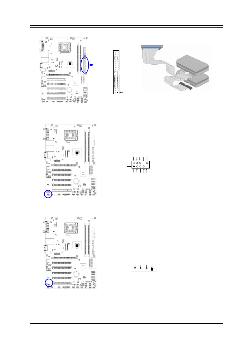
14
IDE Connector
Pin 1
IDE1
2-2-3 Header Pin Definition
(1) Line-Out/MIC Header for Front Panel (9-pin): FP_AUDIO
This header is connected to Front Panel Line-out, MIC connector with cable.
Line-Out, MIC Headers
Pin 1
L
ine
o
ut2
-L
L
ine
ou
t2
-R
S
e
ns
e-
FB
Au
di
o
-
GN
D
LI
N
E
2-
JD
Au
d
i
o-
JD
2
9
10
KE
Y
MI
C
2
-L
MI
C2
-J
D
M
IC2
-R
(2) CD AUDIO-In Headers (4-pin): CDIN
CDIN are the connectors for CD-Audio Input signal. Please connect it to
CD-ROM CD-Audio output connector.
CD Audio-In Headers
CDIN
4
1
GND
CD-R
CD-L
GND
(3) Speaker connector: SPEAK
This 4-pin header connects to the case-mounted speaker. See the figure below.
(4) Power LED: PWR LED
The Power LED header is light on while the system power is on. Connect the
Power LED header from the system case to this pin.