Kemppi Minarc 150 VRD User Manual
Page 6
© KEMPPI OY
6 – MINARC 150 VRD / 0538
3.1.2. TIG welding
In DC TIG welding, the arc between a non-melting tungsten electrode and the welding
piece melts the welding piece, thus forming a weld pool. Arc and electrode are shielded by
an inert shielding gas (Argon). If necessary, filler is used. Filler wire is fed into the weld
pool from the outside of the arc. Filler and rate of welding current is selected on the basis
of diameter of tungsten electrode and welding position.
3.2. OPERATING FUNCTIONS
See also 2.4. Main components and 3.4. Welding selections.
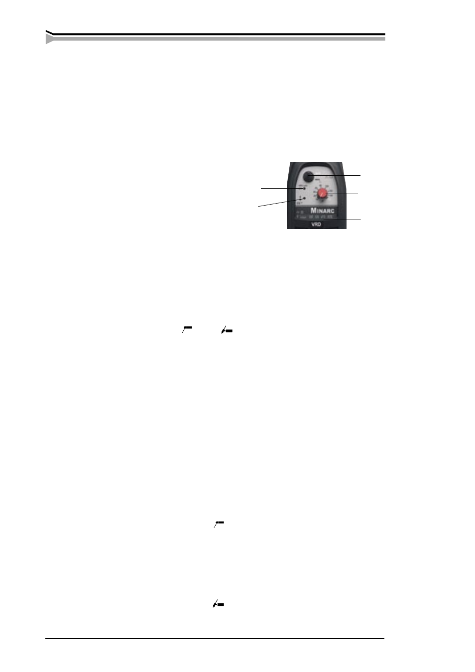
A
Signal light VRD safe ON
B
Welding process selecting switch
C
Welding current adjuster
D
Signal light for overheating
E
Suitable electrodes
Main switch and signal light
When you turn the main switch to position I, signal light on main switch is lit and the unit
is ready for welding. Signal light is always on, when the unit is connected to the mains
and the main switch is in position I.
Note! Always start and stop the machine from the main switch, never use the plug
as a switch!
Signal light VRD safe ON (A) The machine is equipped with an OCV reduction circuit.
The signal light is lit when the circuit is activated and the unit is in working order.
Welding process selector, MMA
/ TIG
(B) Switch is used for selecting either
MMA or TIG welding, depending on welding target. When you have switched the unit
to TIG welding, VRD is constantly active, thus reducing terminal voltage to 30 V. This
facilitates arc cut-off when you stop welding.
Regulating welding current (C) Welding current rate is regulated steplessly with an
adjusting potentiometer.
Signal light for overheating (D) A yellow signal light of overheating is lit, when ther-
mostat has tripped due to the unit’s overheating. Fan will cool the unit and after the signal
light goes off, the unit is again ready for welding.
3.3. WELDING SELECTIONS
3.3.1. Manual Metal Arc welding (MMA)
Select welding parameters according to filler manufacturer’s recommendations.
1.
Select polarity (+ or -) of welding current cable and return current cable according
to filler.
2.
Select MMA welding with the switch
.
3.
Select suitable welding current by adjusting potentiometer according to table of
suitable electrodes (E).
3.3.2. DC TIG welding
Select welding parameters according to filler manufacturer’s recommendations.
1.
Connect TIG torch to - pole and earth cable to + pole
2.
Select TIG welding with the switch .
3.
Select suitable welding current by adjusting potentiometer.
A
B
C
D
E