Divert control logic, Block diagram, 1 block – K-Patents DD-01 User Manual
Page 26: Diagram
Advertising
25
7. DIVERT CONTROL LOGIC
A logical description of the system is provided as a complement to the previous information about the elec-
tronics.
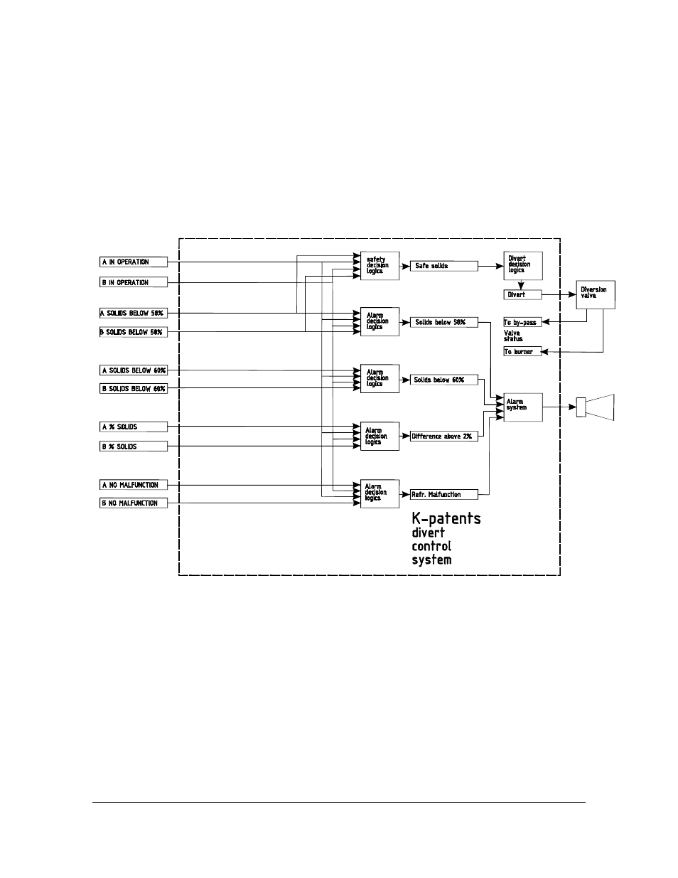
7.1. BLOCK DIAGRAM
The block diagram Figure 7.10 shows the connections between the different logical subsystems.
Figure 7.10
Block diagram of the divert control system
INSTRUCTION MANUAL FOR DD-01
DOCUMENT/REVISION: IMD 1/5
Effective: June 20, 2005
Advertising