Kussmaul Electronics 091-45 User Manual
Page 3
Switch #4 Switch #5 Switch #6 Trips Below:
O F F
O F F
O F F
15.06
Volts
O F F
O F F
O N
14.84
Volts
O F F
O N
O F F
14.63
Volts
O F F
O N
O N
14.42
Volts
O N
O F F
O F F
14.22
Volts
O N
O F F
O N
14.03
Volts
O N
O N
O F F
13.84
Volts
O N
O N
O N
13.66
Volts
(c) Select the desired overvoltage trip point from the column to the far right in table 2 below
(d) Set switches #4, #5, and #6 to the settings below in table 2 corresponding to the
selected trip point in step (c).
(e) Set switch #7 to “RUN” operation if it is not already in that position. This allows
approximately 1 second of time delay for the trip points to act, and filters alternator ripple.
(f) For mechanical installation, refer to figure 3 for the hole pattern and sizes.
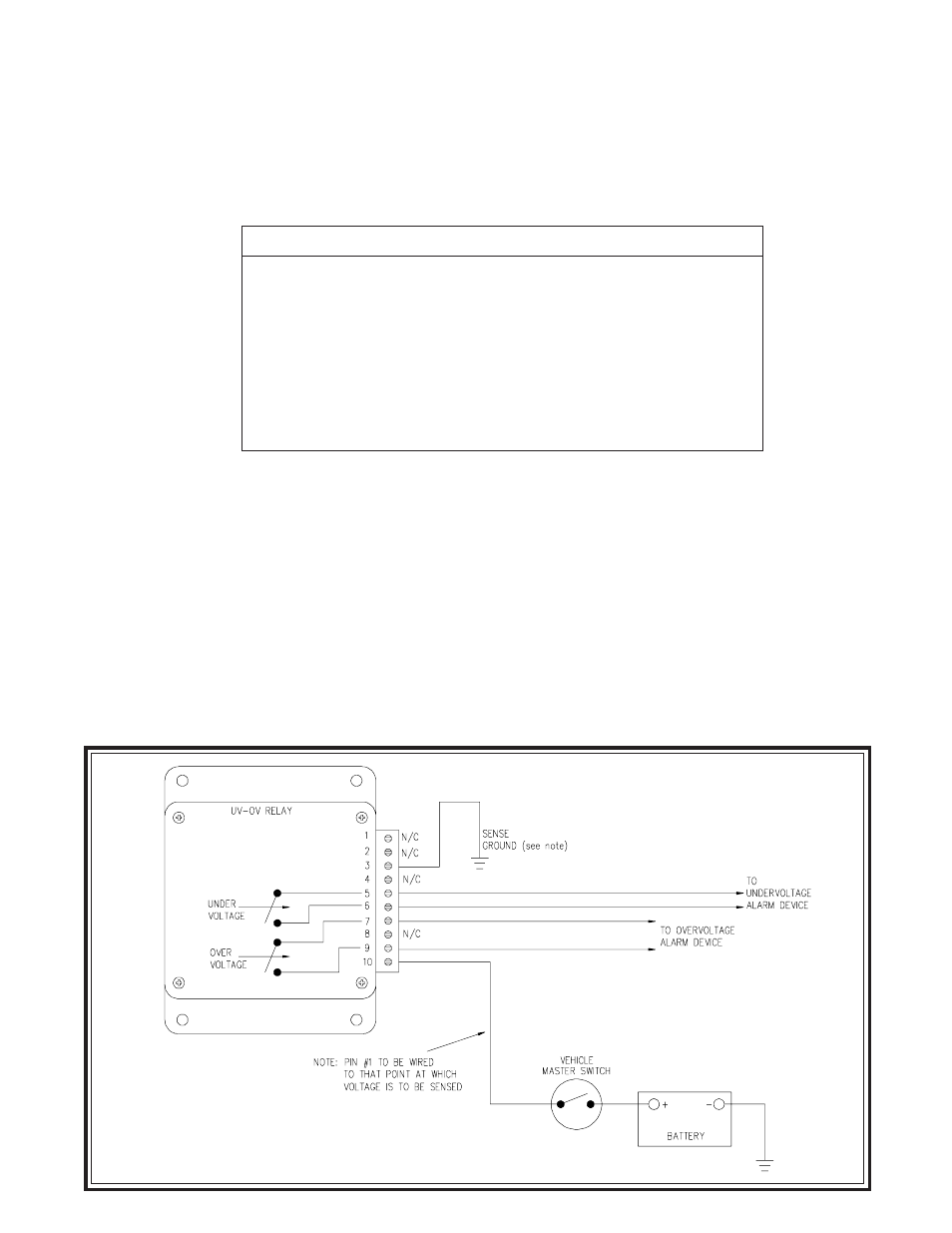
(g) For electrical installation, refer to figure 2 which shows the connections to various
parts of the vehicle. The alarm contacts can be connected to alarm lamps via ground
or +12 volts. Figure 4 shows a scheme for a ground hookup while Figure 5 shows
a hookup for +12 volts.
TABLE 2 Overvoltage Programming
FIGURE 2 Electrical Installation