Installation, Figure 1 – Kussmaul Electronics 091-158 User Manual
Page 3
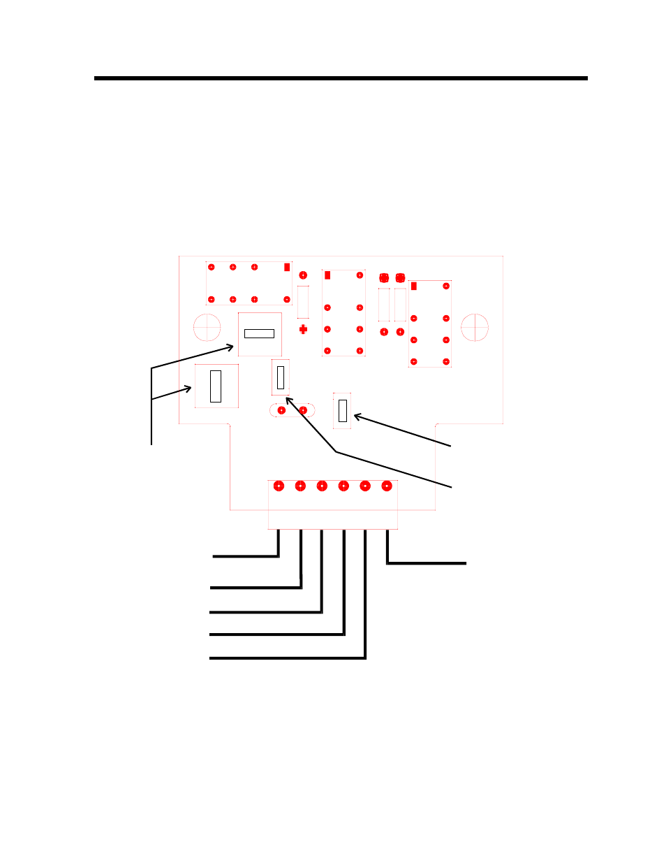
INSTALLATION
Mount the logic module in a dry location away from any sources of heat. Figure
1 illustrates the wiring required. The +12 volts and Ground input are required to
supply the output of the logic module. Note that the input signal may be either a
+12 volts or Ground. The polarity of the input signal is independent of the
polarity of the output. A separate selector switch is provided to select the polarity
of the output. NOTE: DO NOT EXCEED AN OUTPUT LOAD OF 2 AMPERES.
PROGRAMMING SWITCH LOCATIONS AND INSTALLATION WIRING
Input Signal Polarity
AND/OR SELECTORS
Both must be in the
same position
Output Signal Polarity
+12v
+12v
Gnd
Gnd
OR
AN
D
OR
AND
CI1
S3
K1
S2
R3
R2
1
1
1
S4
S1
K3
K2
KUSSMAUL ELECTRONICS INC
091-158-001
1
J1
R1
+12 v
Gnd
Input 1
Input 2
Input 3
1
2
3
4
5
6
OU
TP
UT
SI
G
N
A
L
FIGURE 1
OUTPUT