Kussmaul Electronics 091-28 User Manual
Page 3
170 Cherry Avenue
West Sayville, NY 11796
www.kussmaul.com
Instruction Manual
1. In order to accurately locate the 3 mounting holes first locate the center of the large hole
and mark with a center punch mark. Using a compass scribe 1 3/4" dia. circle.
Locate the bezel over this scribed circle, mark the 3 mounting holes & center punch
each hole.
2. Drill 3 mounting holes, 3/16" diameter. Drill 1 center hole using hole saw or conduit
punch. 1 3/8" diameter.
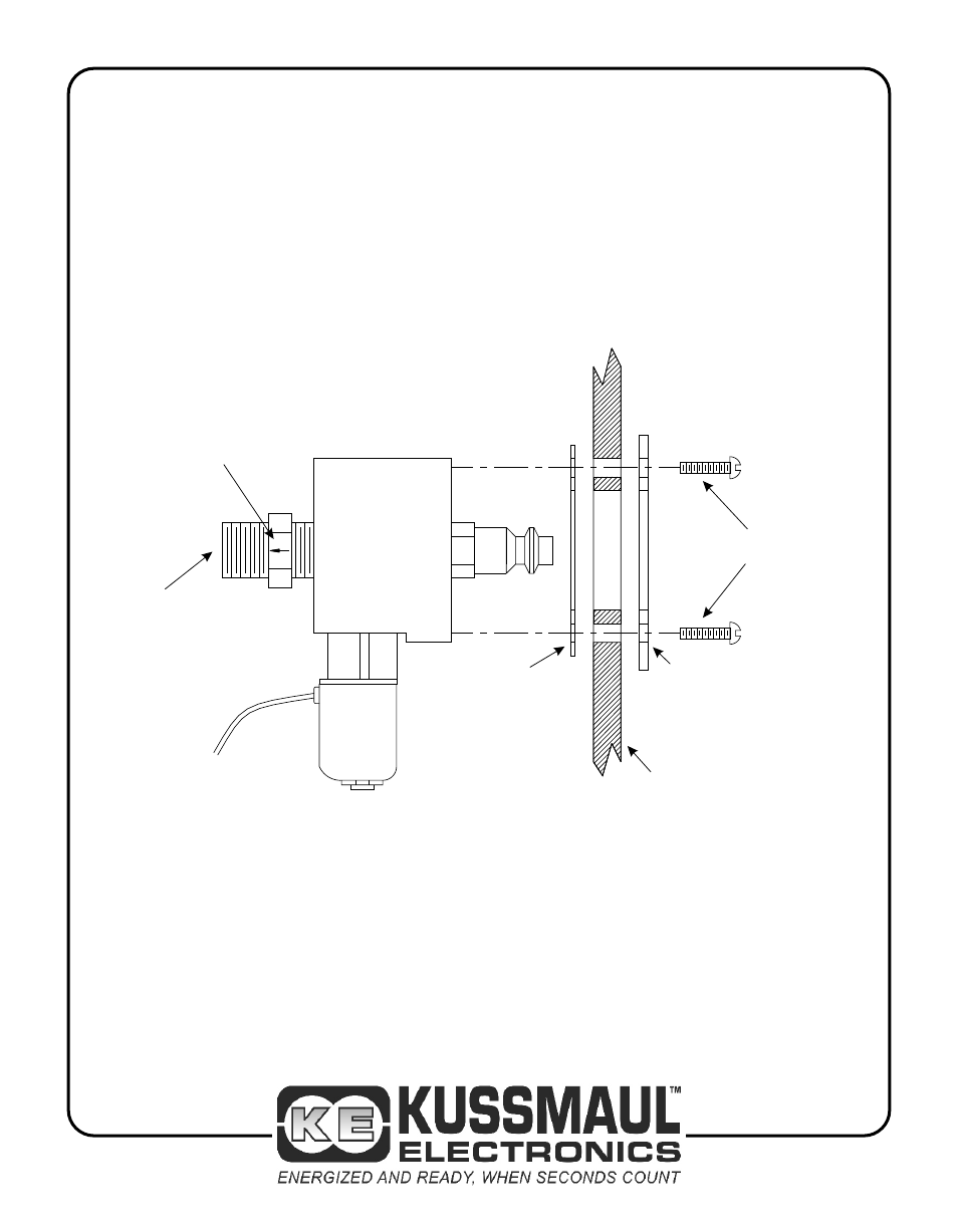
3. Mount the Cylinder Assembly as illustrated in Figure 1.
4. Install the check valve being certain that the arrow on the check valve points away from
the cylinder assembly.
5. Connect tubing as required to vehicle’s air system.
INSTALLATION INSTRUCTIONS
Figure 1
Note Location of Arrow
on Check Valve
Arrow Mark is Very Small
CYLINDER
ASSEMBLY
OUTPUT TO
VEHICLE’S
AIR SYSTEM
GASKET
TRUCK WALL
BEZEL
SCREWS
Ph: 800-346-0857
Fax: 631-567-5826
File: 091-28 rev b.cdr
Rev: B, Date: 1-28-13