Legrand PA120Y User Manual
Page 2
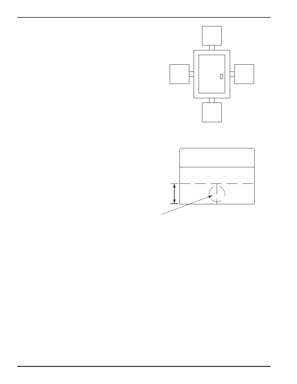
6. Using a hole saw (or knockout device), cut a hole in the SPD
enclosure at the entrance location. The upper edge of the hole
must not exceed 1.3" from the mountable bottom of the SPD
enclosure (see figure at right). Duct hole location must be
centered to the side chosen. Remove any dust, residue and/or
burrs from the SPD housing after making the knockout.
SPD
SPD
SPD
SPD
DUCT HOLE
LOCATION
1.3"
[33MM]
COVER
BASE
PANEL
7.
Put the connecting nipple into the empty SPD enclosure using the appropriate lock nuts and bushing.
8.
Connect the SPD enclosure to the electrical panel by placing the nipple into the knockout hole in the panel using the
appropriate lock nuts and bushing.
9.
Mount the SPD securely using the pre-punched mounting holes and the necessary hardware based on the composition
of the wall.
10. Cut the connecting wire to the appropriate lengths. (Reminder: use maximum #10 AWG stranded connecting wire.)
Connect the SPD terminals to the load side of the circuit breaker in the panel according to the wiring instructions in this
manual. The circuit breaker must be in the OFF position. Run the appropriate conductors from the overcurrent device
in the panel, through the nipple into the SPD unit.
11. Terminate the wires to the appropriate terminal lugs in the SPD. Be careful to connect the wires to the appropriate
standoff following circuit board annotations for phase and reference potentials. The recommended torque for
tightening the terminal lugs to the wire is 25 pounds.
5. Determine the desired location for the SPD. The figure at right
illustrates potential locations for the SPD relative to the panel.
Hold the SPD case to the panel box and mark the location
of the knockout on the SPD case. Make a knockout in the
electrical panel where the SPD is to be installed.
The knockout should be as close to the breaker feeding
the SPD as possible.