Legrand 880MP User Manual
Page 2
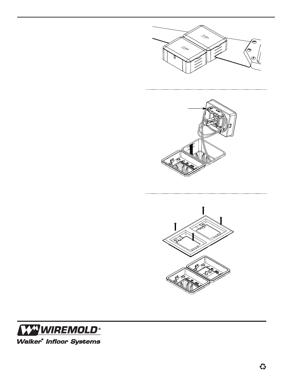
Floor Finishing and Activation:
9. After concrete has cured, saw off the
remainder of the box(es) at floor level
using a wood saw and remove the box
spacer. If the final floor covering is a
thicker than 5/16" [7.9mm], leave enough
of the box protruding above the floor to
compensate (see Figure 4).
10. Wire fill capacity is determined by reading
the first legible volume calibration along
the interior of the box.
11. A cover plate adapter (Cat. No. 880MPA)
is required for each gang or compartment
of the activation. The adapter is installed
by pushing it into the box opening until
firmly seated. The ratchet teeth along
the box interior will retain the adapter
without the use of screws or glue.
12. Bend radius control for fiber optic
communication activations is maintained
by wrapping the cable around the storage
loop on the underside of the cover
adapter prior to installation
(see Figure 5).
13. Attach the trim flange (sold separately)
using four #8-32 screws supplied with trim
flange (see Figure 6).
14. Complete the installation by attaching
the appropriate cover plate option.
Figure 4
Figure 5
Figure 6
Fiber Storage Loop
The Wiremold Company
U.S. and International:
60 Woodlawn Street • West Hartford, CT 06110
1-800-621-0049 • FAX 860-232-2062 • Outside U.S.: 860-233-6251
Canada:
850 Gartshore Street • Fergus, Ontario N1M 2W8
1-800-741-7957 • FAX 519-843-5980
IA0145R2 1202
© Copyright 2002 The Wiremold Company All Rights Reserved